|
Bias Supplies
The bias voltage keeps the quiescent current in the power output valves at the safe design value.
In most amplifiers the HT voltage is not regulated
-it is free to rise and sag in accordance with load current and mains voltage fluctuations.
If the HT (or more particularly the screen voltage in the case of pentodes/tetrodes)
increases, then the quiescent current in the power valves will try to increase too.
To maintain roughly the same operating point and dissipation in the power valves,
the bias voltage must therefore go proportionately more negative as the screen voltage goes more positive.
In other words, if the HT is not regulated then the bias supply must not be regulated either
–they should be allowed to track one another naturally.
In most valve amps the bias voltage can be adjusted over a small range to accommodate differences between valves and
changes due to aging (as they get older their gm falls and less negative voltage is needed for a given operating point).
Sometimes the bias is user adjustable,
but generally it is trimpot inside the amplifier which must be adjusted by someone with at least a rudimentary understanding of what they are doing.
 If the bias is reduced to zero volts then the valve will run red hot (and perhaps be destroyed),
while if it is made very negative then it will reach cut-off.
This covers the full range of useful adjustment from cold class-B to total meltdown.
So how much negative voltage do we need to cover the full range?
That’s easy: just take the screen-to-cathode voltage and divide this by the triode mu of the valve,
i.e. the mu quoted on the datasheet when operating in triode mode.
This will be enough to bias the valve almost to cut-off, and we don’t really need more than that!
The triode mu of some popular valves are:
If the bias is reduced to zero volts then the valve will run red hot (and perhaps be destroyed),
while if it is made very negative then it will reach cut-off.
This covers the full range of useful adjustment from cold class-B to total meltdown.
So how much negative voltage do we need to cover the full range?
That’s easy: just take the screen-to-cathode voltage and divide this by the triode mu of the valve,
i.e. the mu quoted on the datasheet when operating in triode mode.
This will be enough to bias the valve almost to cut-off, and we don’t really need more than that!
The triode mu of some popular valves are:
EL34 = 10
EL84 = 20
KT66 = 7.5
KT77 = 11
KT88 = 7.5
6L6GC = 8
6V6GT = 10
For example, if you’re using a 6L6GC with a screen voltage of 400V,
then aim for a raw negative voltage of:
400/8 = 50V (negative).
By contrast, an EL84 running at 300V would need only:
300/20 = 15V negative.
Remember, this is not the normal operating voltage,
it’s just the maximum voltage worth aiming for so you can then adjust it down to whatever normal operating value you like.
All that is really needed is a simple pot,
but there seem to be as many different bias adjustment circuits found on schematics as there are different amplifiers!
This is somewhat surprising considering how simple the task is.
I’m not going to explain them all; there is really only one worth using.
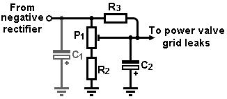
This is about as universal as a passive bias-adjust circuit can get.
C1 is the main bias reservoir capacitor (note the polarity!).
It is good design practice to limit the range of voltage adjustment so it is impossible to reduce the bias to nothing (0V).
This at least gives a modicum of protection against accidental or unskilled adjustment.
This limit is provided by R2 which forms an end-stop for P1, also called an ‘idiot resistor’!
The total resistance of P1+R2 forms part of the power valves’ grid leak resistance, and there will be a maximum allowable value given in the data sheet.
Since we will usually want to make the grid leak resistors as large as possible to avoid loading down the driver stage,
the resistances used in the bias supply need to be small.
A 10k bias pot is ideal. Typically R2 will be roughly equal to P1, but experimentation may be necessary.
R3 is an emergency pull-down resistor.
This ensures that if the pot wiper fails to make good contact with the rack (because it is dirty or worn out, say)
the grid leaks will effectively be connected directly to the raw bias supply through R3 instead,
biasing the valves safely cold.
R3 can have a value of about ten times P1 so it has negligible effect on the rest of the design.
C2 is added to decouple the grid leak circuits from one another (when more than one valve share the same circuit) and simultaneously acts as an RC smoothing filter with P1.
Since the bias supply draws very little current we only need one stage of smoothing in addition to the reservoir capacitor.
Both capacitors are typically 10u to 100u –they’re not critical.
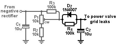 One annoyance caused by a simple bias supply is that when you turn the amp off, the bias caps may discharge faster than the HT caps.
If you flip the amp on again very quickly the valves will therefore draw excessive current which may blow the HT fuse.
This problem can be avoided very simply by inserting an extra resistor and diode before the final bias cap C2.
D2 now allows the cap to charge quickly as usual, but it can only discharge slowly through R4.
The grid leak path is not affected because it is only grid current flowing out of the grid (i.e. through D2) that matters in this respect,
so this mod can be applied to any existing bias network.
Now we need to work back towards the rectifier and transformer.
One annoyance caused by a simple bias supply is that when you turn the amp off, the bias caps may discharge faster than the HT caps.
If you flip the amp on again very quickly the valves will therefore draw excessive current which may blow the HT fuse.
This problem can be avoided very simply by inserting an extra resistor and diode before the final bias cap C2.
D2 now allows the cap to charge quickly as usual, but it can only discharge slowly through R4.
The grid leak path is not affected because it is only grid current flowing out of the grid (i.e. through D2) that matters in this respect,
so this mod can be applied to any existing bias network.
Now we need to work back towards the rectifier and transformer.
Before solid-state rectifiers were available, valve rectifiers were the order of the day.
Most power rectifiers contained two diodes with separate anodes and a shared cathode/heater,
so the familiar two-phase rectifier arrangement was the most convenient.
The bias supply demands hardly any current so it was sufficient to use a half-wave supply which required only one extra (relatively small) diode,
rather than going to the expense of adding a fourth diode for a full-wave supply.
When silicon rectifiers finally appeared they were simply substituted for the old valve rectifiers in many circuits,
which is why the old fashioned half-wave bias supply is commonly used even in new amps.
It’s important to realise that there is nothing special about the bias rectifier;
it works just like the positive part of the power supply,
but it is often drawn differently which makes it appear to have special status.
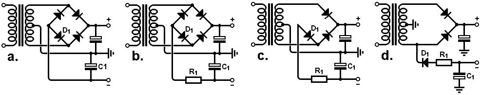
Let’s break it down. The circuit labelled a. is a conventional bipolar power supply.
It looks like a bridge rectifier but really it is a pair of two-phase rectifiers –the pairs of diodes face opposite directions so one pair produces the positive rail while the other produces an equal-but-opposite negative rail.
However, we don’t need as much negative voltage for the bias supply,
so let’s put in a series resistor R1, to drop some voltage (this also means C1 can have a smaller voltage rating).
This takes us to the image in b.
Historically it was expensive to use two diodes, so let’s throw one of them away,
leaving us with the half-wave negative supply in c.
Finally, the circuit in d. is identical to the one in c.,
it’s just been drawn the way you usually see it on amp schematics.
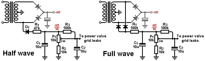
The series dropping resistor R1 forms a potential divider with the bias adjustment circuit and so reduces the average rectified voltage.
Assuming we are using the half-wave rectifier and we need to drop the voltage quite a lot (which is usually true) we can use the following formula:
Vdc = Vrms × 0.45 × Rshunt / (Rshunt + Rseries)
Putting this in terms of the triode mu we get to the unusual formula:
Rseries = Rshunt(0.32 × µ - 1)
For example, if the bias adjustment circuit amounts to 20k to ground, and the mu of the power valves is 10, then we need a series dropping resistor of:
Rseries = 20000 × (0.32 × 10 - 1) = 20000 × (2.2) = 44000 ohms
(the close standard of 47k would probably do since this equation is actually a slight underestimate).
If you decide to use the full-wave version of the circuit then you will need twice the series resistance.
This will give you exactly the same voltage and charge time, but less ripple and less stress on the power transformer.
The completed circuit is shown below.
In some amplifiers the bias is taken from a low-voltage tapping point on the transformer winding.
In such cases no series resistor (or a very small resistor) is required.
In fact, it's more likely the voltage won't be great enough.
If that is the case then either use one of the circuits above, or convert to a voltage doubler as shown below
(you may prefer to use larger values for C1 and C3, otherwise the ripple doubles too).
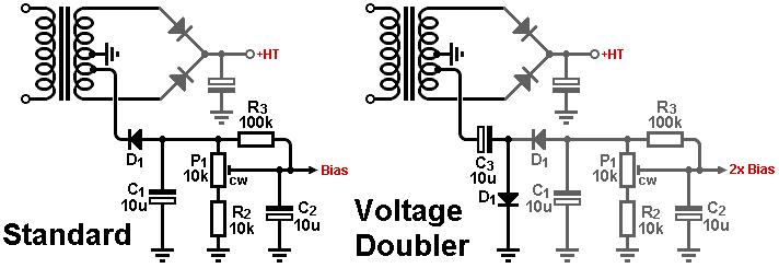
Capacitor Cupled Bias Supply
When you need a bias supply but your transformer has no centre tap (i.e. bridge rectifier) then a cheap dodge is to use a capacitor-coupled bias supply.
The image below shows the basic arrangement with current paths illustrating how it works (R2 represents the bias adjust circuit).
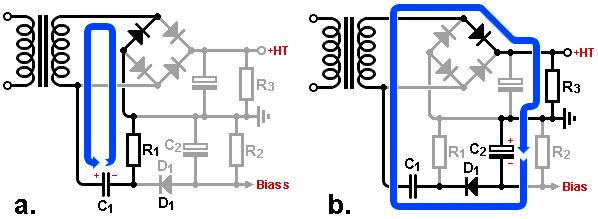
The coupling capacitor C1 initially charges up through R1. Beginners often forget this resistor; it is essential!
The bigger you make C1, the greater the bias voltage achieved; a good compromise is 47n to 220n.
It needs to be rated for more than the peak AC transformer voltage. Use a good quality plastic/poly capacitor.
The optimum condition is then to make R1 equal to about 33k to 47k as this allows the largest negative voltage to be achieved.
On the next half cycle C1 it discharges through D1, into C2. This allows C2 to charge negatively.
The size of C2 does not affect the final bias voltage, only the ripple and charging time –anything from 10u to 47u is typical.
 Notice that this charging path includes the HT load represented by R3.
This means that before the valves have warmed up, there will be no bias voltage present unless you have a bleeder resistor across the HT.
It is therefore a good idea to include a bleeder, and 100k to 220k (2W) is ideal. (Also, the HT reservoir capacitor must be larger than C1, but it always is anyway, so don’t worry about it).
Notice that this charging path includes the HT load represented by R3.
This means that before the valves have warmed up, there will be no bias voltage present unless you have a bleeder resistor across the HT.
It is therefore a good idea to include a bleeder, and 100k to 220k (2W) is ideal. (Also, the HT reservoir capacitor must be larger than C1, but it always is anyway, so don’t worry about it).
The bigger you make R2 (the bias adjust circuit), the greater the available negative voltage.
It is a good idea to make it larger than R1 otherwise loading becomes excessive. However, it can’t be too large since it forms part of the output valves’ grid leak path.
This also makes this sort of bias supply unsuitable for powerful amplifiers with big/multiple output valves that need a low-impedance grid leak path.
A good compromise is to use a 47k bias pot; an end-stop resistor will then raise the total above R1.
This should be fine for anything up to 50W amp.
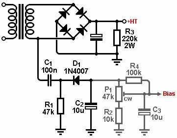
The completed circuit is shown on the right (drawn in the more familiar arrangement) with a typical bias-adjust network.
This circuit is fairly universal and will generate a negative voltage a little greater than one tenth of the HT, making it suitable for use with most power valves.
C1 can be increased if more negative voltage is needed.
|