The Valve Wizard |
|
Menu |
The cascode is a means of using a pair of triodes to achieve very high levels of gain and input sensitivity from a single stage. For guitar amps it can be imagined to be a simulation of a pentode, and indeed the circuit does resemble one. It has high gain, high ra and very low input capacitance just like a pentode, but without the inherent drawbacks of noise, microphonics and expense. The two triodes are usually of the same type for the sake of simplicity and convenience, but they do not have to be. Hi gm triodes provide the most gain, and the ECC82 or 6SN7 work remarkably well as cascodes. The ECC83 will work to, though it is a little more fiddly to set up.
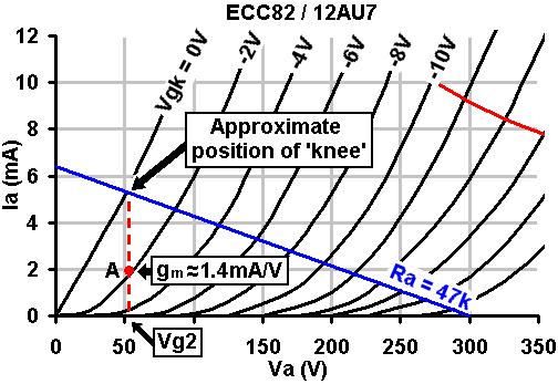
There is more than one way to go about designing a cascode, but this
is how I do it. Firstly, a cascode's characteristics look a lot like
a pentode, except that they are shifted to the right by an amount equal
to the lower triode's quiescent anode voltage, as seen
in the oscillograph. The lower triode's anode voltage is more-or-less
equal to the upper triodes grid voltage, which we will call the 'screen
grid', Vg2,for simplicity. The higher the screen voltage, the higher the gm and therefore the
gain, but the lower the output signal swing, because the curves move
further towards the right. The peak-to-peak output signal swing is limited
to HT-Vg2. With most valves, a screen voltage in the region of 80V seems
to be ideal, although with low gm valves it may need to be higher. We begin by looking at the normal anode-characteristics of the LOWER triode. We will assume that the screen voltage is equal to the anode voltage of the lower triode. Draw a line from this voltage up to the 0V grid curve; this indicates where the 'knee' will occur. Knowing the HT we can now choose a load and draw a load line in the usual way, to see if it passes through, above or below the knee, and adjust the screen voltage if necessary. In this case I have chosen an ECC82, and HT of 300V and a tentative screen voltage of 55V. It is clear that a 47k load will pass right through the knee (I adjusted the screen voltage so it would, of course! You may prefer to make the load line pass below the knee, for an even more 'pentode-ish' sound). Note, the blue line is NOT the actual load line that the lower triode will operate on, it's merely a design aid. The bias point of the lower triode must lie on the vertical red line.
For centre bias, it will be half-way up of course. Wherever you decide
to put it, read off the gm (transconductance). In this case it is about
1.4mA/V. Because the lower triode generates all the current swing, its
gm decides the gm of the whole cascode, and this allows us to immediately
predict the gain, which is the same as for a pentode:
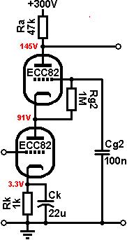
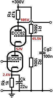
Biasing the Lower Triode: This is done in the usual way. Looking at the chosen bias point we see that the bias voltage is about -2V and the anode current is2mA. Applying Ohm's law: 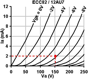
All that remains is to
bias the upper triode. From the chosen bias point above, we can see
that the quiescent current is 2mA. The voltage dropped across the anode
resistor must therefore be 0.002 * 47000 = 94V. The voltage across the
lower triode is 55V, so that leaves: Fixed Biasing the Upper Triode: The textbook arrangement is
to feed the screen grid from a potential divider from the HT. The upper
grid does not draw any current, so we require only a voltage reference
and as such, R1 and R2 can be made high in value so as to present a
negligible load to the power supply. If we choose a value of 560k for
R1 and apply the formula for a voltage divider we can find R2: Alternatively, a string of zener diodes could set the grid voltage rock-solid. A bypass capacitor should still be used to shunt zener noise though. Grid-leak biasing the Upper Triode: Alternatively we can create a self-biased version by simply using a grid-leak resistor on the upper triode, and a large grid-bypass capacitor. At quiescence, the upper triode is zero-biased of course, but when we input a signal a charging current flows into the capacitor via the grid-leak, which lowers the voltage on the screen grid. The larger the signal, the greater the bias developed, which creates a subtle compression effect on sustained passages, rather like power-supply sag. This method is simple and works well for guitar. The grid leak should be a typical value, say 1Meg. The time constant
produced by Rg2 and Cg2 should be at least equal to the time period
of the lowest frequency which is to be amplified at full gain. The value
of Cg2 may therefore be chosen according to: Note that the measured quiecent voltages will different from the expected -as shown by the completed circuit on the right- because the upper triode is zero biased. Only under full drive will the average current fall and the voltages shift back towards the expected values. Output impedance: Assuming the cathode is bypassed, the cascode
has a total ra approximately equal to: Total Gain: The gain of the cascode is equal to:
Heater considerations: Since the cathode of the upper triode is at a high voltage, it may be necessary to elevate the heater supply to avoid exceeding the maximum rated heater to cathode voltage. In this case it is not necessary, but it is always worth checking. |
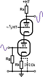 The operation of the circuit is simple:
The lower triode amplifies in the normal way. The amplified (and inverted)
signal is passed from the lower anode to the cathode of the upper valve.
The signal voltage on the cathode then modulates the current flowing
through upper triode, allowing the signal to be amplified yet again
(non-inverting this time). The grid of the upper valve is kept at a
fixed voltage (more or less) to provide the correct bias for the upper triode. Overall
the output signal in out of phase with the input.
The operation of the circuit is simple:
The lower triode amplifies in the normal way. The amplified (and inverted)
signal is passed from the lower anode to the cathode of the upper valve.
The signal voltage on the cathode then modulates the current flowing
through upper triode, allowing the signal to be amplified yet again
(non-inverting this time). The grid of the upper valve is kept at a
fixed voltage (more or less) to provide the correct bias for the upper triode. Overall
the output signal in out of phase with the input. 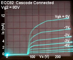
 R2 = R1 / (HT - Vg2) * Vg2