|
Minimalist Valve Curve Tracer
When I first started getting into electronics, one of the first really useful things I designed and built for myself
was a curve tracer. A curve tracer is like the ultimate valve tester, displaying the anode characteristic curves in real
time on an oscilloscope with X/Y capability (most two-channel scopes have this).
My first design was understandably naive in its implementation and would only test small triodes, but it worked OK
(and still does). All the curves in my book were done using it. Since then, more and more DIY curve tracers have
begun to appear on the internet. These have tended to increase in complexity, often interfacing with a PC.
A particularly fine example is the u-Tracer. I decided it was about time I built a new tracer that would test small
pentodes as well as triodes, but instead of increasing the complexity, I chose to go in the opposite direction:
What is the simplest curve tracer I could come up with? The result is a minimalist design which actually uses fewer
parts than my very first beginner efforts!
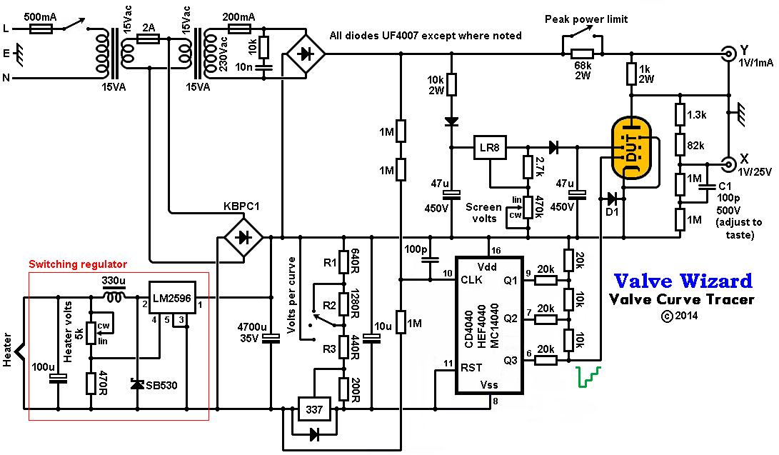
The circuit can be broken into four functional blocks:
Anode supply
Control-grid (bias) supply
Screen-grid supply
Heater supply.
 Anode Supply:
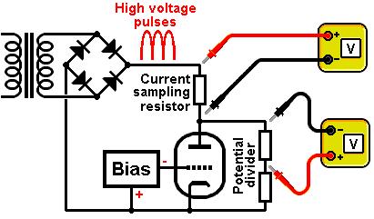
The anode voltage needs to sweep from zero up to a high value. A classsic way to do this is simply to rectify the AC
voltage from a transformer and apply it directly to the valve, as shown in the firgure. To trace a curve we need to
measure the anode current and anode (to cathode) voltage, and plot them using the X/Y oscilloscope function.
The current is measured by adding a 'current sampling resistor' in series with the valve, and measuring the voltage across it.
Ohm's law tells us the current: I = V/R.
The anode voltage is scaled down with a potential divider rather than expose the voltmeter (oscilloscope)
to the full high-voltage pulses. I used several resistors in series so they share the high-voltage stress, so 1/4W
resistors can be used throughout the design, except where noted.
This divider is partially bypassed by capacitor C1.
This compensates for cable capacitance which otherwise leads to looping/double traces. You may need to adjust the value of
C1 to suit your cables (my cables are rather long which is why I needed a rather large 100pF of compensation).
Notice that the negative voltmeter probes are both connected to the same point (the anode). This is an awkward necessity,
because most oscilloscopes share the same 'ground' connection between both channels.
Therefore, during use, the anode is safe to touch while the grid and cathode are at high (negative) voltages- the oppsite of what we are used to!
I used back-to-back 15V transformers to generate the required voltages. Not only is this a cheap solution,
it also minimises the leakage currents between the mains and high-voltage supply which otherwise flow to earth
via the oscilloscope, also causing some 'looping' or double traces.
I also added a resistor to limit the peak current (power) that can flow in the valve.
This is useful when setting up, in case the valve has been configured wrong.
It is also useful for looking at the curves of triode-connected pentodes
when the anode is not used, i.e. when the screen grid is used as a low-power anode.
 Control-Grid Supply:
The control grid supply is the bias supply, and is usually the trickiest part of a curve tracer to do well, especially if you're aiming for simplicity.
To trace each grid curve the circuit must step the grid-cathode voltage from 0V down to negative voltages in a staircase fashion.
Ideally it should jump from one value to the next when the anode voltage is at its highest or lowest peak, otherwise you see the transitions on the screen as fine 'hairs' or interference.
To test various different valves, we need the size of the bias voltage steps to be variable or switchable between say, 0.5V steps, 1V steps, or 2V steps.
In my design the staircase waveform is generated using a 4040 binary counter IC. The binary output from this chip is fed into an R2R-ladder. This is a standard way of converting a binary number into an analog voltage,
and is really a type of digital-to-analog- converter! This circuit uses only three bits of the counter, which means there are 2^3 = 8 bias steps. Each step happens one every mains cycle (1/50Hz), and I found that eight
steps produces a reasonably steady display on screen. Using more steps (i.e. tracing more grid curves) leads to a flickering display because it takes too long to go through the complete bias cycle.
To synchronise the bias steps with the anode voltage pulese, the pulses themselves are fed to the clock input of the counter (via a high resistance to protect the chip!). Some tweaking was required to get the
counter to transistion when the anode voltage drops close to zero. It's still not absolutely perfect -you can see some retraces on pentode curves- but for a simple circuit it's good enough.
You may be used to thinking of logic chips running off positive supply voltages, where a binary count of 000 would
correspond to zero vots while a count of 111 would result in the maximum positive voltage.
Be we need negative voltages here, so in this case the chip operates from a negative supply.
A binary count of 000 now corresponds to the maximum negative voltage, while a count of 111 result in the maximum
voltage, which is zero (relative to cathode).
Changing the size of the voltage steps is easy: just change the supply voltage to the counter IC.
This is done with a 337 negative voltage regulator and a three-way switch (actually a double-throw centre-off switch).
This means the circuit requires no calibration since the accuracy of the negative supply voltage is determined quite satisfactorily by the accuracy of the regulator and resistors (use 1% devices).
The awkward-value resistors shown in the schematic are in practice made up from the following standard values:
640 = 620 + 20 ohms
1280 = 1.1k + 180 ohms
440 = 220 + 220 ohms
Diode D1 between grid and cathode protects the bias supply from a direct short between anode and grid (if this happens the HT fuse with blow).
 Screen-Grid Supply:
To test pentodes the screen voltage must be held constant relative to the cathode.
This sometimes requires a completely separate power supply just for the screen, which I wanted to avoid.
Therefore, in my design the screen-grid supply comes from the main anode supply. Since the main anode supply is already full-wave rectified, all that is needed is a reservoir capacitor to get smooth(ish) high-voltage DC.
An extra diode is needed to block this DC voltage from 'getting back' onto the anode supply, though.
The charging pulses into the first 47u capacitor lead to ringing in the power transformer (aka diode switching noise). This leads to a small but noticeable 'bump' in the grid curves. This is cured by using UF4007 fast rectifiers, and by adding an RC
snubbing network across the transformer. The value of the resistor should be tweaked to suit your transformers (i.e. use a trimpot at first, then replace it with a fixed resistor). I found 10k to work best for me.
The raw DC is regulated by an LR8 high-voltage adjustable regulator IC. This is the only part that might be hard to find, especially outside America (I got mine on eBay). Nevertheless, I decided it was worth using because it results in an extremely simple circuit and, more importantly, has built-in protection against thermal and current overloads.
Screen grids tend to be fragile, and I like the fact that the LR8 won't deliver more than about 20mA and will shut down if it overheats. OK, this also limits the testing only to small pentodes that don't need lots of screen current,
not big bottles (except at very low screen voltages), but I would rather have a bullet-proof circuit that is immune to user error. The diode in series with the scren grid protects the regulator (and potentiometer) from reverse bias such as would occur with an anode-screen short circuit. This makes the circuit practically indestructible.
The screen voltage can be varied up to about 218V, and I added a 10k resistor in series with the incoming DC to share some of the dissipation, so the regulator does not start shutting down so soon when the screen voltage is set to typical values.
A cheap moving-coil analog meter indicates the screen voltage (not shown on the schematic).
Heater Supply:
The first power transformer provides 15Vac which is rectified to produce about 20Vdc for the heater and grid supplies.
In my old curve tracer I used an LM317 to make a variable heater supply. This of course wastes rather a lot of power,
and since I used a fairly small power tranformer, it could only manage about 500mA for short periods.
In this new design I used a switching regulator. This makes far more efficient use of the available power, so I can supply at least 1A heaters without trouble, from the 15VA transformer (note that the switching regulator must use a Schottky diode; an ordinary diode won't work).
In my prototype I actually used a ready-made regulator PCB which are readily available from Chinese sellers on eBay; cheaper than I could build it from scratch.
A cheap digital voltmeter indicates the heater voltage (not shown on the schematic).
It is important to note that the heater regulator shares a common connection with the valve cathode, so the heater-cathode insulation is never stressed.
Remember, in this design the anode is actually earthed through the opscilloscope, so everything "below" the anode is actually bobbing up and down below zero volts, including the heater and grid supplies!
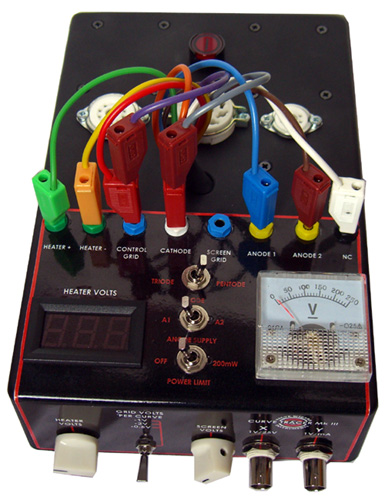
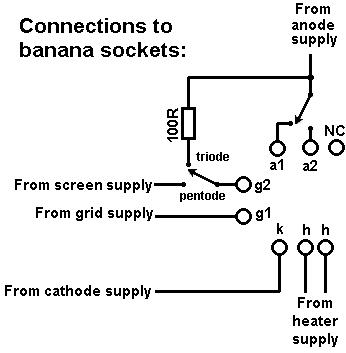 External Connections:
I used three valve sockets: 7-pin (B7G), 8-pin (octal), and 9-pin (B9A), but you could add more.
All the pins are connected in parallel, that is, pin-1 to pin-1, pin-2 to pin-2 etc.
The pins are then brought out via nine colour-coded wires (using the standard resistor colour code). In other words, the brown wire is connected to pin-1 on every socket, the red wire is connected to pin-2 on every socket, etc.
These have banana plugs that can be inserted into panel-mounted sockets.
I used two banana sockets for the anode connection, with a switch to swap between them. This way I can quickly flip between two triodes in one envelope (grids and cathodes connected together).
I further added a switch to connect the screen-grid socket either to the screen-grid supply for ordinary pentode operation, or to the anode supply through a 100R resistor for triode-connected operation.
One final socket has no connection and simply provides a place of rest for any unused cables.
Using the Instrument:
The curves will appear in mirror image to how we normally view them, but this is easy to put up with. If your scope has an 'invert' option on the X-input then you can use it to reverse the curves back to normal (my scope doesn't).
I have chosen values so that 1mA through the valve corresponds to 1V vertical deflection on the scope,
and 25V anode-to-cathode voltage corresponds to 1V horizontal deflection. Since most scopes have ten squares on
the graticule, this means the whole width of the graticule can correspond to 250V, which is about as high as the anode
voltage will go in this circuit.
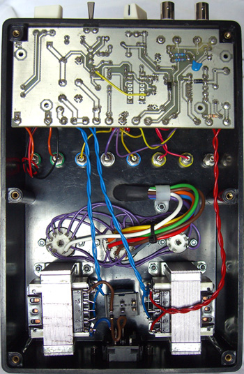
There is no PCB for this project as it was purely experimental. You'll have to lay out your own!
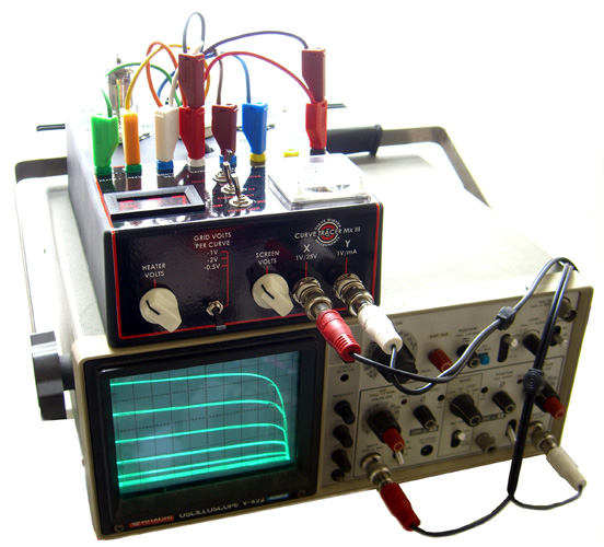
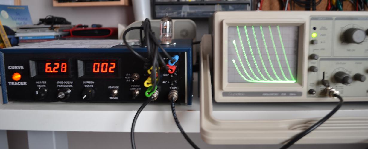
Below is a picture of DanGu's version of the ValveWizard minimalist tube curve tracer.
He chose to add a rotary switch to select different values of compensation capacitor C1, to optimise the tracing.
He also found it necessary to use a 1nF capacitor (instead of 100pF) connected to the CLK pin of the 4040, to ensure proper triggering on the 2V/grid curve setting.
His curves look even better than mine!
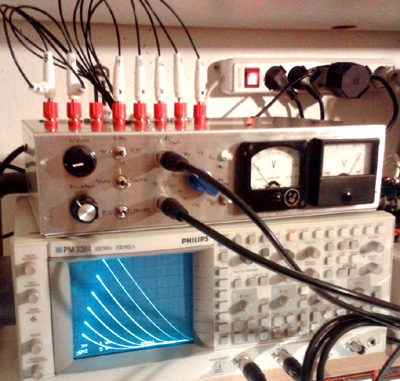
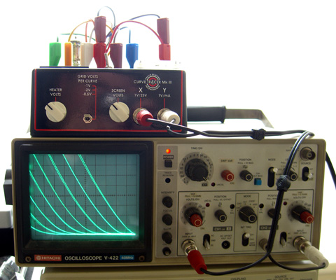
Below is a picture of Jan G's version of the ValveWizard minimalist tube curve tracer.
He also added switcheable values for C1, and for the capacitor connected to the CLK pin of the 4040.
|