|
The Direct-Coupled Cathode Follower
 The cathode follower found in many guitar amps appears unremarkable. It usually drives a tone stack, which would otherwise
present quite a heavy load to a 'normal' gain stage. The cathode
follower can drive this load with less attenuation and less harmonic distortion. The cathode follower found in many guitar amps appears unremarkable. It usually drives a tone stack, which would otherwise
present quite a heavy load to a 'normal' gain stage. The cathode
follower can drive this load with less attenuation and less harmonic distortion.
However, the cathode follower found in guitar amps does more than meets the eye. As well as driving the tone
stack, it often has as much effect on overdrive tones as any other stage in the preamp, and very high-gain amps often contain more than one direct coupled cathode follower.
It works so well for overdrive tones because it was originally "badly designed" from the textbook point of view, which turned into a happy accident.
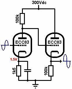
The circuit universally consists of an ECC83/12AX7 gain stage, direct coupled to the cathode
follower, each with 100k load resistors. So what makes this circuit
so interesting? Load lines will reveal the truth. In this example we will use a 300V HT, although the actual voltage is not
critical for obtaining good results.
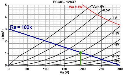 The first load line shown here is for the gain stage. The bias point could be set almost anywhere
along it, although somewhere in the middle is usual, in this case -1.5V (green dot), making the
idle anode voltage about 195V. This is the first reason why the circuit is badly designed;
the anode voltage of the gain stage is "too high", and we'll see why shortly. The first load line shown here is for the gain stage. The bias point could be set almost anywhere
along it, although somewhere in the middle is usual, in this case -1.5V (green dot), making the
idle anode voltage about 195V. This is the first reason why the circuit is badly designed;
the anode voltage of the gain stage is "too high", and we'll see why shortly.
The load line below is for the cathode follower. Remember, the x-axis shows anode-to-cathode
voltage, but we are also interested in the cathode-to-ground voltage. This can be easily added
by reversing the anode voltage scale, since when no anode current flows, the cathode voltage
would be zero. This scale has been added to the top of the graph.
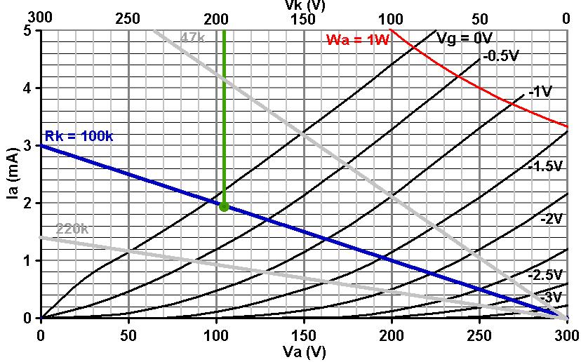
We know that for
normal operation the cathode will be a couple of volts higher than the grid (which is
connected to the anode of the previous stage and is therefore at 195V), but for simplicity we
will assume it is at the same voltage as the grid, or 195V.
Looking at the load line, for a cathode voltage of 195V the bias point appears to be very nearly on the 0V grid curve. In reality we know that the cathode should be a couple of volts more
positive than this, but that simply pushes the bias point even further up the load line! The
problem is, by having a high anode voltage on the previous stage, we are forcing the cathode
follower to bias so hot that it will be on the edge of drawing grid current. This will drag down the
anode voltage of the previous stage and simultaneously raise the cathode voltage of the follower,
increasing its bias. Eventually an equilibrium point will be reached where the grid current generates
enough bias to prevent any further increase in grid current. In other words, the valves will come
to rest with grid current permanently flowing into the cathode follower (experimentation suggests
about 0.4mA or so). All this happens automatically at switch-on of course.
This is the second reason why the stage is badly designed; we 'should' have used a triode
with a much lower anode resistance, such as an ECC82, which would make the grid curves steeper and would allow more conventional biasing. Another option would have been to increase the follower's
cathode load resistor, to say 220k (shown in faint on the graph) which would also allow a
more normal bias point of about -0.75V.
 So we have a cathode follower
that is permanently 'stealing' current from the previous stage; what
is the result? If a down-going signal appears at the gain stage's anode
the grid voltage of the follower is pushed down back into the area of
normal operation, and grid current stops flowing for the duration of that half cycle.
But when the incoming signal is positive-going the grid is pushed more positive, which induces even more grid
current to flow into the cathode follower as it tries to maintain bias, which
in turn 'drags down' the anode voltage of the gain stage which is trying
to move positive. In other words, the up-going cycles are very heavily
compressed, but the down going ones are not, which generates a lot of
second harmonic distortion. But since the two stages are DC-coupled, there can be no blocking distortion, only smooth 'compressive' clipping.
This freedom from blocking distortion is one of the reasons this circuit is often used in high gain amps.
The distortion can be increased by reducing the cathode follower's load resistor, to
say, 68k, 56k or even 47k. A 47k load line is also shown in faint on
the graph above, and clearly shows that the bias point wants to be well
above the 0V grid curve- so considerable grid current will flow, and experimentation
suggests this is around 0.8mA at idle. This causes even more compression, and
is perhaps the easiest way to warm up the tone of an amp- the difference
is immediately obvious, and far better value-for-money than fiddling
around with coupling capacitor types or carbon comp' resistors. So we have a cathode follower
that is permanently 'stealing' current from the previous stage; what
is the result? If a down-going signal appears at the gain stage's anode
the grid voltage of the follower is pushed down back into the area of
normal operation, and grid current stops flowing for the duration of that half cycle.
But when the incoming signal is positive-going the grid is pushed more positive, which induces even more grid
current to flow into the cathode follower as it tries to maintain bias, which
in turn 'drags down' the anode voltage of the gain stage which is trying
to move positive. In other words, the up-going cycles are very heavily
compressed, but the down going ones are not, which generates a lot of
second harmonic distortion. But since the two stages are DC-coupled, there can be no blocking distortion, only smooth 'compressive' clipping.
This freedom from blocking distortion is one of the reasons this circuit is often used in high gain amps.
The distortion can be increased by reducing the cathode follower's load resistor, to
say, 68k, 56k or even 47k. A 47k load line is also shown in faint on
the graph above, and clearly shows that the bias point wants to be well
above the 0V grid curve- so considerable grid current will flow, and experimentation
suggests this is around 0.8mA at idle. This causes even more compression, and
is perhaps the easiest way to warm up the tone of an amp- the difference
is immediately obvious, and far better value-for-money than fiddling
around with coupling capacitor types or carbon comp' resistors.
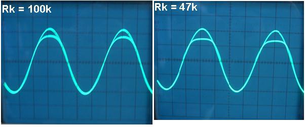
The oscilloscope traces below show a ~20V p-p, 1kHz output from the cathode
follower and the input signal to the gain stage's grid (which has been
inverted and scaled for comparison). Notice how only the positive part
of the cycle is affected, clearly demonstrating the heavy compression
and also the increase in compression for a lower load resistance.
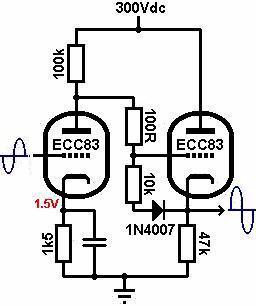
A Useful mod for DC-coupled cathode followers:
 It is very common to
see a DC-coupled cathode follower in a guitar amp, often before a tone
stack. The traditional arrangement suffers from the problem that on
start up, the grid will immediately rise to HT potential while the cathode
is still cold, at ground potential. This can sometimes cause
arcing between the electrodes, destroying the valve (I have burnt out a few
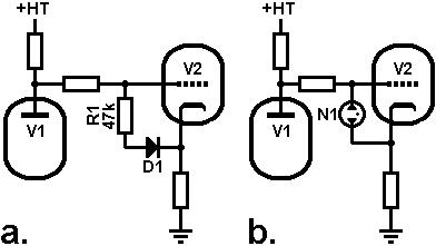
this way). This problem can be easily corrected by connecting an ordinary
rectifier diode (such as a 1N4007) between grid and cathode. At start up, this will keep the cathode within
a volt of the grid. Once hot, the valve will bias with
the cathode at a higher potential than the grid and the diode will be
reverse biased, off. It is very common to
see a DC-coupled cathode follower in a guitar amp, often before a tone
stack. The traditional arrangement suffers from the problem that on
start up, the grid will immediately rise to HT potential while the cathode
is still cold, at ground potential. This can sometimes cause
arcing between the electrodes, destroying the valve (I have burnt out a few
this way). This problem can be easily corrected by connecting an ordinary
rectifier diode (such as a 1N4007) between grid and cathode. At start up, this will keep the cathode within
a volt of the grid. Once hot, the valve will bias with
the cathode at a higher potential than the grid and the diode will be
reverse biased, off.
When reversed biased a diode acts more-or-less like a capacitor, which a capacitance of the order of 10pF. This is not a worry
though, because capacitances between the grid and cathode are reverse bootstrapped to a much smaller valve, less than 1pF.
Another solution [diagram b] is to use an ordinary neon bulb
(not the kind advertised as mains indicators as these have a resistor
built in). The neon will strike if the grid-cathode voltage exceeds
about 90V, which is about as high as it is safe to go with preamp valves
Bootstrapping for more gain: 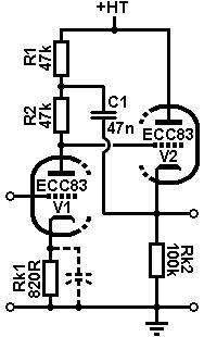
Because the cathode follower acts as an impedance buffer we can use
it to 'bootstrap' the previous stage. This is done by splitting the
previous stage's anode resistor into two equal parts and connecting
a capacitor from the cathode follower's cathode, to the junction of
the two resistors [see right]. The cathode follower then effectively multiplies
or bootstraps the value of the lower anode resistor R2, making it look
like a constant-current source. This will increase the gain of the previous
stage so it becomes almost equal to the mu of the valve! An added bonus
is that if you don't use a cathode-bypass capacitor, the gain is still
very hgh (about 85-90 with an ECC83). Leaving the cathode unbypassed
reduces blocking distortion and reduces 'fizzy' sounding overdrive,
giving better crunch. Usually you sacrifice a lot of gain though, but
not in this case! So I guess you can have you cake and eat it
too...
|