The Valve Wizard |
|
|
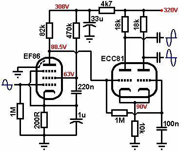
The differential pair (long tailed pair) is a phase inverter with two inputs, which amplifies the voltage difference between the two. The signals on each grid are mixed, and balanced outputs are taken from the anodes. A long-tailed pair usually has a little more output signal swing than a cathodyne using the same valves (but not as much as some 'techs' might suggest), and it has the advantage of providing some gain. As a quick rule of thumb, a long tailed-pair has about half the gain of a simple gain stage using the same valve, and takes about twice as much input signal to cause clipping. It is usual to use two identical triodes, usually within the same envelope. High mu, valves are well suited. The ECC81 (12AT7) is a good choice (surprisingly!), although the 12AY7 (no European equivalent) seems to be even better in terms of tone and makes a good replacement for an existing circuit. The ECC83 (12AX7) has the highest gain of course and will be the most easy to overdrive, but it has the least output signal swing, so is the best choice for amps which focus on preamp distortion. The ECC82 (12AU7) is an excellent choice for a clean / bass amp. The following example uses an ECC81 (12AT7), and the HT is 320V. Firstly we should decide how much voltage to allow across the triodes, and how much can be spared for the tail. The more we allow for the tail, the better the balance, but the lower the maximum output signal swing and the greater the risk of strange distortion artefacts like 'swirl'. If you already know the quiescent anode voltage of the preceeding stage, you may be able to choose this for the tail voltage if it is not too high.
Biasing: Choose a bias point to taste. Hot-to-centre biasing will encourage the power valves to distort more, before the phase inverter does, while colder biasing will reveal more phase-inverter distortion, tipping the tonal balance in favour of the preamp.
Since we know the cathode must be at 90V and we chose Vgk to be -1.5V, the grid must be at 90 - 1.5 = 88.5V. We could either force the anode voltage of the previous stage to match this (which would probably require a pentode since it is a fairly low voltage) or set it using a potential divider, etc. The second grid must also be at exactly the same DC potential. This is applied from the first grid via a high value grid resistor or "pull-up resistor" (Rg), usually the same value as the grid-leak in a normal gain stage, or 1Meg in this case. The second grid should be grounded at AC, so it is decoupled with a capacitor (Cg). It needs to leak all frequencies to ground and can be chosen in conjunction with the value of grid resistor (1Meg). For a low roll-off of 1Hz:
Because we did not use a real constant-current sink, the two outputs will not be perfectly balanced if both triodes have the same gain (although balance will be pretty good all the same). This is because the first triode acts as a cathode follower with a gain of slightly less than 1. Therefore the second triode is being driven with a signal slightly lower in amplitude than the first triode, so its output will also be slightly lower. We can correct this by making the gain of the second triode slightly higher than that of the first. This can be done by making its anode resistor 10% to 15% higher than that of the first triode. (Or conversely, by making Ra1 roughly 10% to 15% smaller than Ra2, of course). Many classic amps use 82k and 100k anode resistors for this. However, if the tail resistor is more than about 10k the balance is actually very good with eqaul-value anode resistors, and using 82k and 100k actually makes the balance worse again! Fortunately, a little imbalance produces a pleasant tone, causing extra 2nd harmonic distortion in the phase inverter and power stage. Gain: The gain of the differential pair is exactly the same as that of a normal stage, and looking at the load line, the gain is about 32 (ignoring the loading effect of the following stage). The only difference is that the gain is shared between the anodes, so a 1V input will produce a 16V signal on each anode. The voltage difference between each anode is therefore 16 + 16 = 32 as calculated, but to only one anode the gain is half the calculated value. This is not a problem since we will probably be driving the differential pair so hard that we will obtain large output signals. Looking at the load line the maximum output signal swing from grid-current to cut-off is about 135V peak to peak, more than enough to overdrive most power valves. Output impedance: Heater supply: Because the cathode has been placed at a high voltage, you should always check the data sheet to see whether an elevated heater supply will be necessary. In most cases it won't be, unless you are using a bi-polar power supply or something else unusual that leads to a very high heater-to-cathode voltage. In the previous example we chose a suitable cathode voltage first, and assumed that we could set the grid voltage to match. However, if you already know the quiescent anode voltage of the preceding stage (say 100V) and you want to directly couple the anode to grid of the differential pair, you immediately know the grid voltage of the differential pair. Subtract this from the HT and draw a load line as discussed already and choose a bias point. As an example, Vgk might be -2V, therefore the cathode must be at 100 + 2 = 102V and you can use Ohm's law to find the value of tail resistor as discussed. Although this may result in an odd value, using the nearest standard value is still alright since all the voltages will settle naturally and will still be close to the ones you designed for. Tweaking can then be done once a working prototype has been built. |
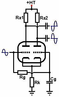 The cathodes of the two triodes are connected together, and one grid is usually grounded at AC.
The first triode acts as both a normal inverting gain stage, and as a cathode follower. The signal on the cathode drives the second triode which is non-inverting. The circuit produces perfectly balanced outputs when the anode loads are equal and the cathodes are connected to a constant current sink. If the total current through the two triodes is constant, increasing the current through the first MUST cause the current through the second to decrease by exactly the same amount, and vice versa.
Perfect balance is preferred for hifi, but for a guitar amp we can easily replace the constant current sink with a large 'tail' resistor instead. The larger the resistor the more it will approximate a constant current sink and the better the balance, although it cannot be too large or it will reduce maximum output signal swing. Because of this large 'tail' resistor (or current sink) the differential pair is affectionately known as the "long tailed pair".
There are several versions of the long tailed pair (also known as the Schmitt inverter), and the one requiring the least components is this DC coupled version.
The cathodes of the two triodes are connected together, and one grid is usually grounded at AC.
The first triode acts as both a normal inverting gain stage, and as a cathode follower. The signal on the cathode drives the second triode which is non-inverting. The circuit produces perfectly balanced outputs when the anode loads are equal and the cathodes are connected to a constant current sink. If the total current through the two triodes is constant, increasing the current through the first MUST cause the current through the second to decrease by exactly the same amount, and vice versa.
Perfect balance is preferred for hifi, but for a guitar amp we can easily replace the constant current sink with a large 'tail' resistor instead. The larger the resistor the more it will approximate a constant current sink and the better the balance, although it cannot be too large or it will reduce maximum output signal swing. Because of this large 'tail' resistor (or current sink) the differential pair is affectionately known as the "long tailed pair".
There are several versions of the long tailed pair (also known as the Schmitt inverter), and the one requiring the least components is this DC coupled version.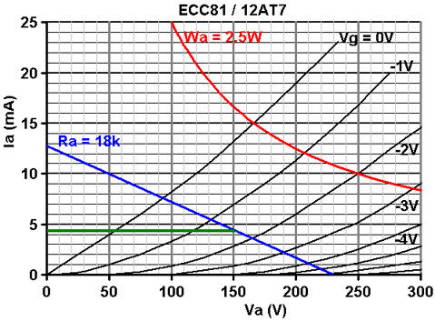
 Unless the differential pair is driving a stage that is guaranteed Class A1 at all times (which it won't be), the output impedance of the differential pair will vary as the load on each anode varies. When the load on each anode is equal, output impedance is the same as for a normal gain stage: