|
Heater / Filament Supplies
Heater Basics
 A valve heater is simply a length of tungsten wire which gets red hot when you shove current through it, so its not much different from a light bulb.
The valves used in guitar amps are indirectly heated (except for some rectifier valves discussed shortly),
meaning the heater is a completely separate and not electrically connected to any other part of the valve.
This means they can be supplied with AC voltage straight from a transformer,
although they can be supplied with DC too, to eliminate hum.
A valve heater is simply a length of tungsten wire which gets red hot when you shove current through it, so its not much different from a light bulb.
The valves used in guitar amps are indirectly heated (except for some rectifier valves discussed shortly),
meaning the heater is a completely separate and not electrically connected to any other part of the valve.
This means they can be supplied with AC voltage straight from a transformer,
although they can be supplied with DC too, to eliminate hum.
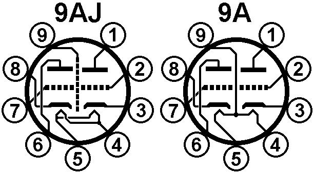
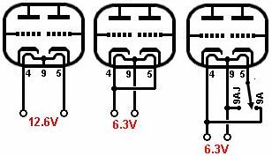 The ECC83 / 12AX7 has a '9A' pinout, which has three connections to the two heaters.
This means they can either be run in series from a 12.6V supply or in parallel from a 6.3V supply.
The ECC81 / 12AT7, ECC82 / 12AU7, and 12AY7, also have the same pinout.
Many other noval valves such as the ECC88 / 6DJ8 and 6N2P have a '9AJ' pinout which only allows the heaters to be operated in parallel from 6.3V (pin 9 is connected to internal shield).
If you're into tube rolling then you can use a double-throw switch to select between one pinout or the other.
The ECC83 / 12AX7 has a '9A' pinout, which has three connections to the two heaters.
This means they can either be run in series from a 12.6V supply or in parallel from a 6.3V supply.
The ECC81 / 12AT7, ECC82 / 12AU7, and 12AY7, also have the same pinout.
Many other noval valves such as the ECC88 / 6DJ8 and 6N2P have a '9AJ' pinout which only allows the heaters to be operated in parallel from 6.3V (pin 9 is connected to internal shield).
If you're into tube rolling then you can use a double-throw switch to select between one pinout or the other.
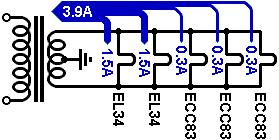 Most power transformers designed for valve amps have a 6.3V heater winding, and all the heaters are run in parallel from it.
The transformer must have enough current capability to manage the total current draw of all the heaters.
For example, the ECC83 data sheet quotes 300mA at 6.3V, so three bottles would together amount to 900mA.
A pair of EL34s would add another 3A to this. You get the idea.
If the transformer doesn't have enough current rating then you can use a small, separate transformer, just for supplying extra heaters.
If that is the case then you're free to use 12.6V (a 12V transformer is close enough) if you want to, or whatever suits the design.
Most power transformers designed for valve amps have a 6.3V heater winding, and all the heaters are run in parallel from it.
The transformer must have enough current capability to manage the total current draw of all the heaters.
For example, the ECC83 data sheet quotes 300mA at 6.3V, so three bottles would together amount to 900mA.
A pair of EL34s would add another 3A to this. You get the idea.
If the transformer doesn't have enough current rating then you can use a small, separate transformer, just for supplying extra heaters.
If that is the case then you're free to use 12.6V (a 12V transformer is close enough) if you want to, or whatever suits the design.
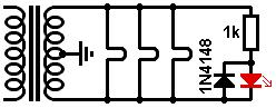 Traditionally, an indicator lamp was often run off the heater supply too.
These days we can use LEDs.
However, LEDs are not built to withstand much reverse voltage,
so it is a good idea to put a diode (or another LED) in anti-parallel with an LED on an AC supply.
This diverts reverse current around the LED and keeps the reverse voltage across it to one diode drop
(and it also reduces DC magnetisation in the transformer).
Traditionally, an indicator lamp was often run off the heater supply too.
These days we can use LEDs.
However, LEDs are not built to withstand much reverse voltage,
so it is a good idea to put a diode (or another LED) in anti-parallel with an LED on an AC supply.
This diverts reverse current around the LED and keeps the reverse voltage across it to one diode drop
(and it also reduces DC magnetisation in the transformer).
Hum in Heater Supplies
Hum and buzz is caused by leakage current between the heater and cathode, and by the electromagnetic field around the heater and associated wiring.
The magnetic field modulates the electron stream inside the valve, leading to hum.
The electric field couples into the audio circuit (especially the grid and anode) via stray capacitance.
You might think that the stray capacitance would be too small to couple low-frequency hum, and you'd be right,
except that the mains supply -and therefore the AC heater voltage- is not a very clean sinewave.
The peaks are usually clipped off by rectifier action, and who knows what industrial motors pollute the supply with hash.
These ugly corners and spikes contain high-frequency enegry which couples quite easily through even tiny capacitances.
This leads to more of a buzz sound than a low hum.
There are various way to deal with these noise sources.
Rule number one is that the heater supply must have a DC connection to audio ground.
This may be a direct connection or an elevating circuit (see shortly).
This is equally true for AC or DC supplies.
Leaving the heater supply floating will result in almighty hum due to primary-to-secondary transformer leakage current,
and is a common beginner’s error.
AC heater supplies should also be balanced to suppress the EM field.
Not only does this reduce the magnitude of the voltage on each wire
(e.g., each wire carries 3.15V rather than one wire carrying 6.3V and the other zero),
but the opposing fields will tend to couple equal-but-opposite hum signals into the audio circuitry,
which should cancel each other out.
Transformer Centre Tap
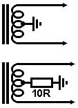 The traditional way to reduce hum is to use a transformer with a centre tap, and connect it to ground.
A refinement is to ground the centre tap through a small flame-proof resistor (anything up to 100 ohms).
This will act as a fuse if there is a short between the anode and heater pins of the power valves,
thereby reducing collateral damage.
The traditional way to reduce hum is to use a transformer with a centre tap, and connect it to ground.
A refinement is to ground the centre tap through a small flame-proof resistor (anything up to 100 ohms).
This will act as a fuse if there is a short between the anode and heater pins of the power valves,
thereby reducing collateral damage.
Artificial Centre Tap
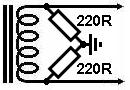 If the transformer doesn't have a centre tap then you can create an artificial one using a pair of resistors.
The resistors should have a fairly low resistance to help shunt leakage currents from the transformer primary.
Values of 100R (1/2W) or 220R (1/4W) are typical.
They will of course consume a little extra current from the transformer
(32mA when using 100R resistors at 6.3V) so bare this in mind.
If the transformer doesn't have a centre tap then you can create an artificial one using a pair of resistors.
The resistors should have a fairly low resistance to help shunt leakage currents from the transformer primary.
Values of 100R (1/2W) or 220R (1/4W) are typical.
They will of course consume a little extra current from the transformer
(32mA when using 100R resistors at 6.3V) so bare this in mind.
Humdinger
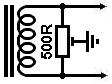
The ways in which hum are induced into the audio circuit are rarely perfectly symmetrical.
Often you will find that minimum hum occurs with an 'off-centre' tap.
This can be done using a trimpot with its wiper grounded to create the artificial centre tap.
Again, a low value is preferable, and a 500 ohm pot will dissipate less than 80mW at 6.3V.
This 'humdinger' pot can then be adjusted on test for minimum audible hum, which seldom occurs at the exact centre setting.
Heater Elevation
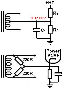 Elevation means referencing the heater supply to a DC voltage other than ground or zero volts.
The heaters still operate at 6.3V or whatever, but this floats on top of the elevation voltage.
Some valve stages such as cathode followers require the heater supply to be elevated to avoid exceeding the valve's Vhk(max) rating.
But even when not explicitly needed, elevation can reduce hum in AC-heated circuits by reducing or saturating the leakage current between heater and cathode.*
Elevation means referencing the heater supply to a DC voltage other than ground or zero volts.
The heaters still operate at 6.3V or whatever, but this floats on top of the elevation voltage.
Some valve stages such as cathode followers require the heater supply to be elevated to avoid exceeding the valve's Vhk(max) rating.
But even when not explicitly needed, elevation can reduce hum in AC-heated circuits by reducing or saturating the leakage current between heater and cathode.*
The DC voltage is applied to a transformer centre tap, artificial centre tap, humdinger, or whatever reference connection the heater supply would normally have.
The elevation voltage can be taken from a potential divider across the HT (it doesn't matter where you position the divider),
and an elevation voltage around 30 to 60V is typical.
The divider should have a fairly high resistance so as not to waste current,
although the lower arm (R2) should not be excessively large or Rhk(max) may be grossly exceeded,
so it is advisable not to make it greater than 100k.
The elevation voltage should be decoupled/smoothed with an arbitrarily large capacitor (C1), say 10uF or more.
Another convenient source of elevation voltage is the cathode of a cathode-biased power valve.
No current flows ‘into’ the heater supply from here, so the power valve bias is not affected.
Dropping Heater Voltage
The heater voltage should be kept within +/-10% of its nominal value for optimum valve performance.
For 6.3V heaters that means 5.7V to 6.9V, though it is even better to stay within +/-5% if you can (6V to 6.6V).
Many guitar amps suffer from rather excessive heater voltages.
This is sometimes because mains voltages are higher today than they were when the transformer was orignally designed
(this is common in the US where wall voltages have risen from around 110V to 117V today).
Sometimes it is because the transformer is more powerful than it needs to be,
i.e. it is not fully loaded so the voltages are not pulled down to their nominal values.
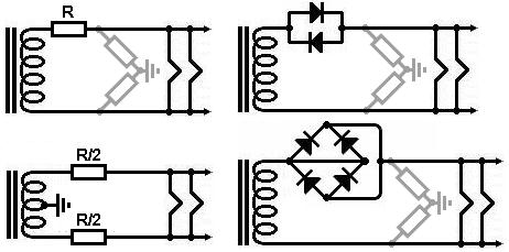 An obvious way to lower the voltage is to add a resistor in series with the heater supply.
For example, if you need to drop 1V and the heater chain draws 3A then you'll need a 1V/3A = 0.33 ohm resistor,
and it will dissipate 1V × 3A = 3W, so it should be rated for 5W or more.
However, if you have a grounded centre tap then a single resistor would upset the hum-balancing,
so it would be better to use two resistors, one in each leg.
These would need to have half the resistance and would dissipate half as much as the single resistor.
An obvious way to lower the voltage is to add a resistor in series with the heater supply.
For example, if you need to drop 1V and the heater chain draws 3A then you'll need a 1V/3A = 0.33 ohm resistor,
and it will dissipate 1V × 3A = 3W, so it should be rated for 5W or more.
However, if you have a grounded centre tap then a single resistor would upset the hum-balancing,
so it would be better to use two resistors, one in each leg.
These would need to have half the resistance and would dissipate half as much as the single resistor.
A less obvious option is to use a pair of diodes in anti-parallel.
On an AC supply this will reduce the RMS voltage by about 0.7V by 'coring out' part of the waveform.
The diodes need to have an average current rating that exceeds the heater current (1N4007s are only rated for 1A!).
Sometimes it is easier to buy a beefy bridge rectifier than indvidual diodes,
in which case you can wire the bridge to create a pair of anti-parallel diodes.
Also, large bridge rectifier packages often have a hole in the middle so they can be conveniently bolted to the chassis.
Valve Rectifiers
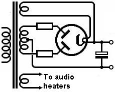 Some small valve rectifiers EZ81 / 6CA4 are indirectly heated and can be run from the same heater supply as the other valves in the amp.
Most, however, are either directly heated (i.e. the heater and cathode are one and the same)
or the heater is connected internally to the cathode.
This is to avoid the need for very thick heater-cathode insulation.
If the heater and cathode are connected then the rectifier will need its own separate heater supply (usually 5V).
This supply rides on top of the HT voltage -it's really an extreme example of heater elevation.
A valve rectifier requires no heater balancing since the HT has bigger noise problems to worry about (i.e. ripple voltage).
Some small valve rectifiers EZ81 / 6CA4 are indirectly heated and can be run from the same heater supply as the other valves in the amp.
Most, however, are either directly heated (i.e. the heater and cathode are one and the same)
or the heater is connected internally to the cathode.
This is to avoid the need for very thick heater-cathode insulation.
If the heater and cathode are connected then the rectifier will need its own separate heater supply (usually 5V).
This supply rides on top of the HT voltage -it's really an extreme example of heater elevation.
A valve rectifier requires no heater balancing since the HT has bigger noise problems to worry about (i.e. ripple voltage).
Layout / Lead Dress
The lead dress of AC heater supplies is very important to minimise hum.
AC heater wires emit significant EM radiation and should be routed well away from all signal wires.
The heater wiring should be neatly twisted to encouragee the radiated fields to cancel out.
Loose twists are useless!
The wiring loom should be pushed into the corners of the chassis where possible.
It helps to orientate the valve sockets so the heater wiring can approach the valve from the corner of the chassis by the shortest path.
When heaters are wired in parallel, the power valves should be first in the heater chain where the current is greatest,
followed by driver valve / phase inverter, with the input stage being last in the chain where EM fields are weakest.
You can of course run seperate wiring looms to different valves as desired.
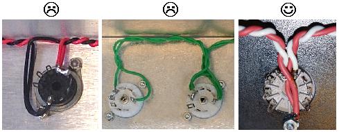 When running ECC83 / 12AX7s on 6.3V, the connection to pin-9 should jump straight over the socket and straight back again.
It should not loop around the outside of the socket as this creates a hum loop.
This is a common beginner's (and professional's!) error.
Do your best to keep the twisting tight right up to the socket.
When running ECC83 / 12AX7s on 6.3V, the connection to pin-9 should jump straight over the socket and straight back again.
It should not loop around the outside of the socket as this creates a hum loop.
This is a common beginner's (and professional's!) error.
Do your best to keep the twisting tight right up to the socket.
DC Heaters
Sometimes no amount of good wiring, balancing and heater elevation will bring hum down to acceptable levels.
In that case we may have to resort to DC heater power, which unfortunately adds complexity.
It must be clean DC; dirty DC can sometimes cause more hum.
 Usually, most hum is picked up by the input valve.
A cheap trick is to supply only the input valve heater with DC while the rest still receive AC.
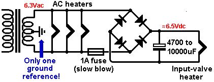
You still need a surprisingly large amount of reservoir capacitance to get the ripple voltage down to acceptable levels;
at least 4700uF for one 300mA heater.
Usually, most hum is picked up by the input valve.
A cheap trick is to supply only the input valve heater with DC while the rest still receive AC.
You still need a surprisingly large amount of reservoir capacitance to get the ripple voltage down to acceptable levels;
at least 4700uF for one 300mA heater.
A 6.3Vac transformer supply, after rectification and accounting for losses and diode drop, will yield about 6.5Vdc.
You can of course adjust this to something closer to 6.3V with a dropping resistor, but this is rarely necessary.
Another important thing to be aware of is that rectifying AC to DC in this way introduces a power-factor loss of about 0.5, which loads down the transformer more.
In other words, to supply a heater with 300mA of DC the transformer actually has to deliver about 600mA of AC,
So be careful not to overload the transformer.
A common beginner's error is to try to add a ground reference on both sides of the rectifier.
This will short out the rectifier!
Only one ground reference is required (centre tap, humdinger, elevation, whatever).
It can be on either side of the rectifier; the other side will received its reference through the rectifier.
(Actually, you can spot this mistake in the Mesa Dual Rectifier and Carvin Legacy amps which foolishly use artifical centre taps on both sides of the rectifier,
so maybe it's not such a beginner's error!)
If you do add a rectifier it is a good idea to add a fuse too, as rectifiers have a nasty habit of failing short.
You can avoid the need for a very high-value fuse by putting it after the AC heaters but before the rectifier.
*See: Cooper, C. E. (1944). Valve Hum. Electronic Engineering, (July), pp72-5.
|