|
IV-18 Clock
This project has been on my list for years.
I bought some Russian IV-18 tubes long ago when I was first becoming interested in valves, before I ever studied electronics at university.
At one point I even considered selling them, thinking I would never get round to using them.
I'm glad I didn't, because I'm quite pleased with the result.
I looked at several IV-18 clock designs people had built and published online, especially this useful page, but most used the rare and expensive MAX6921 VFD driver chip.
It's convenient for sure, but I've never paid Ł10 for one IC and I refuse to start now!
I decided instead to drive the tube with optocouplers. Admittedly my design calls for four of them, which isn't a whole lot cheaper than one MAX6921, but I already had them.
About the IV-18
A VFD is a vaccum flourescent display.
It's basically a directly-heated triode whose anode is coated with phosphor so it glows when current flows
(this is different from a nixie tube which is a simple glow-discharge diode that requires no heater).
You use a VFD just like a triode, with minor details.
The supply voltage is normally much lower than for audio valves; typically 20 to 50V.
You usually have to drive the grid positive (e.g. from the same anode supply) to switch the triode 'on', and pull it to ground to switch if 'off'.
The filament is best driven with AC otherwise you may get a brightness gradient along its length, although this doesn't seem to be a big problem with the IV-18 as it has a folded heater.
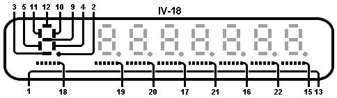
The IV-18 contains eight 7-segment displays; the pinout is shown here.
Each of the segments is an anode, so you can think of each digit as a 'triode' with seven anodes!
However, to avoid the need for dozens of connections, each similar segment is connected together across all the digits.
You therefore need to multiplex the display.
In other words, you apply voltage to the anodes to create the desired number/symbol, then you switch on one of the grids to display the symbol in the correct position on the display.
Now repeat this process for the next position on the display, and the next, and so on, very fast so it appears to be a persistent image to the human eye.
The Circuit
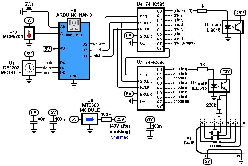
My circuit is built from a few cheaply available modules, plus a couple of shift registers, and some optocouplers to control the 'high' voltage.
The modules are:
Arduino Nano;
DS1302 real time clock;
MT3608 boost converter.
All of them came from Chinese eBay sellers for Ł1 to Ł2 each.
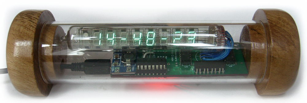
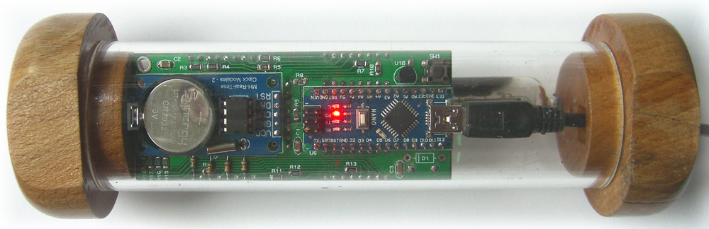
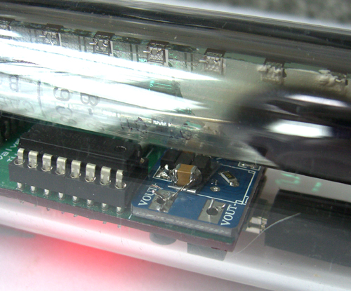
The whole clock is powered from the USB supply of the Arduino Nano. You can see the Arduino and RTC on the underside of the PCB.
Time is kept by a DS1302 Real-Time Clock module.
This module contains an RTC chip, crystal, and a backup battery.
Once the RTC is programmed with the current time/date it will keep accurate time for as long as it has power -which is provided by the battery if the USB power source is absent.
The Arduino simply polls the RTC to ask it for the current time/date, and displays it on the VFD.
My source code also includes a function that automatically takes care of British Summer time / GMT changes, so you should comment this out if you don't want this feature.
The clock displays the time, then every 30 seconds or so the date scrolls across the display (actually it alternates between date and temperature each time).
I included a button (you can see it in the top-right corner of the pcb shown above) for setting and adjusting the time manually.
Pressing it once stops the display on hours, and pressing and holding the button increments the number.
Pressing it once more returns to the clock display.
The next time you do it, it displays the minutes instead, ready for incrementing.
The third time is for seconds, then days, months, and finally the year.
It's a somewhat cumbersome system but it's supposed to be done very rarely if at all, since the RTC has the backup battery to keep it going.
Data from the Arduino is clocked serially into a pair of 74HC595 8-bit shift registers. The first register controls the VFD grids and the second controls the anodes.
Each shift register output drives an optocoupler which switches the high voltage onto the relevent VFD pin.
Originally I didn't include any pull-down resistors on the anodes; this prevented them from switching 'off' fast enough and caused ghosting on the display.
It worked fine once I added them. Interestingly I don't get the same effect from the grids which have no pull downs.
 For a bit of fun I decided to add an MCP9701 temperature sensor, because I had some lying around unused.
This IC puts out an analog voltage proportional to temperature.
The Arduino reads the voltage with its ADC and displays the temperature every 30 seconds or so.
It's not super accurate, in fact I should probably change the source code to show half-degrees instead of the 0.1-degree precision it currently displays.
Curiously, when you first power on the circuit, the ADC readings are always way off for the first minute or so, even though the sensor is outputting the right voltage.
I still don't understand why this happens but it settles down after the first two or three cycles, so I ignore it.
For a bit of fun I decided to add an MCP9701 temperature sensor, because I had some lying around unused.
This IC puts out an analog voltage proportional to temperature.
The Arduino reads the voltage with its ADC and displays the temperature every 30 seconds or so.
It's not super accurate, in fact I should probably change the source code to show half-degrees instead of the 0.1-degree precision it currently displays.
Curiously, when you first power on the circuit, the ADC readings are always way off for the first minute or so, even though the sensor is outputting the right voltage.
I still don't understand why this happens but it settles down after the first two or three cycles, so I ignore it.
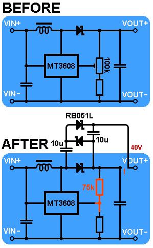
 The MT3608 boost converter makes up to 25V from the 5V supply.
However, while this is enough to light the VFD brightly with a static display, it looks rather dim when you start multiplexing it.
I couldn't find a higher-voltage converter in a small enough package (if you don't need such a small package you could use an XL6009 module which will do up to 50V), and I'd already had the PCBs made,
so I chose to modify the module by adding a voltage doubler to the output.
The necessary changes as shown here; you can just see the mod in the photo, it's the cluster of components underneath the VFD tube.
I replaced the trimmer with a fixed resistor to give me 40V fixed output, but only because the trimmer was preventing me from squeezing it all into my acrylic tube -you could leave the timmmer alone if you prefer.
The MT3608 boost converter makes up to 25V from the 5V supply.
However, while this is enough to light the VFD brightly with a static display, it looks rather dim when you start multiplexing it.
I couldn't find a higher-voltage converter in a small enough package (if you don't need such a small package you could use an XL6009 module which will do up to 50V), and I'd already had the PCBs made,
so I chose to modify the module by adding a voltage doubler to the output.
The necessary changes as shown here; you can just see the mod in the photo, it's the cluster of components underneath the VFD tube.
I replaced the trimmer with a fixed resistor to give me 40V fixed output, but only because the trimmer was preventing me from squeezing it all into my acrylic tube -you could leave the timmmer alone if you prefer.
The Mount
The clock is mounted inside a 45mm diameter (39mm bore) acrylic tube, also from eBay China.
It's a tight fit and I was lucky it fitted at all, since I had the PCBs made long before I thought about how I was going to mount anything!
I painted the edges of the PCB with nail varnish because it was scratching the acrylic every time I slid it in and out.
The stop-ends are made from some wood I found on the side of the road, turned on my lathe.
I drilled and filed a hole in one end for the mini-USB cable.
I turned the stop-ends to be almost too large to fit, then I heated the tube with an air gun so it would expand, and shoved them in.
They were also tacky with new varnish so they seem to be firmly stuck now.
Not sure how easy it will be to replace that RTC battery one day!
The Firmware
I don't know if anyone else will be interested in building this project, but just in case, you can download my Arduino sketch here.
You will also need to download the DS1302 library from Rinky-Dink Electronics.
When you first program the Arduino you will need to uncomment the part of my code that programs the RTC with the current time (enter the correct time for you, obviously).
However, this means the Arduino will reprogram the RTC every time it resets (e.g. every time you power up), so after programming it once you need to comment out those lines again, and program the Arduino a second time.
The RTC will then retain the correct time.
You may also want to comment out the line dealing with British Summer/Winter Time, and the line that displays temperature if you don't want that feature.
|