|
U-Boat: Sub-Octave / Synth Effect
 Sub-octave effects have always been rare, and even rarer in the DIY world. In fact, to my knowledge no one has
ever designed a DIY smooth sub-octave effect! At least no one on the internet. Until now that is...
Sub-octave effects have always been rare, and even rarer in the DIY world. In fact, to my knowledge no one has
ever designed a DIY smooth sub-octave effect! At least no one on the internet. Until now that is...
Until now the only way to make a smooth sub-octave was to copy the Boss OC-2 or EH Octave Multiplexer, or one of
their close bretheren (probably 90% of the commercial sub-octaves are indistinguishable from the Boss circuit). Finally, however, the U-Boat fills the gaping void, making it unique in the DIY world. It offers
the tracking performance of the OC-2, a synth sound rather like the EH, yet the circuit is simpler than both! Just one knob? How is that possible?
Well, the switch selects between a smooth sound or a synth sound, and the knob blends this with the dry signal. At one extreme is pure
dry signal, and the other is pure effect. An internal trimpot allows the loudness of the sub-octave to be adjusted to suit your gear. In other words,
you get ALL the control of the OC-2 from one knob (But no double-sub-octave, sorry).
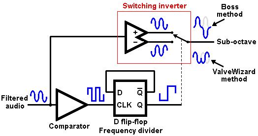 Before looking at the circuit it will be helpful to review the usual method of analog frequency division. As shown in the figure on the left,
the basic approach is to covert the audio into a square wave logic signal whose frequency is divided by two using a textbook D flip-flop circuit. The
resulting signal is then used to control a switching circuit that alternately inverts one cycle of the original audio.
Before looking at the circuit it will be helpful to review the usual method of analog frequency division. As shown in the figure on the left,
the basic approach is to covert the audio into a square wave logic signal whose frequency is divided by two using a textbook D flip-flop circuit. The
resulting signal is then used to control a switching circuit that alternately inverts one cycle of the original audio.
All commercial pedals
that the author is aware of use the Boss method, which inverts on the peak of the audio. This gives the smoothest sub-octave sound, but it is very difficult to
build a switching circuit that works down to small signal levels, and reliably generating the control signal is also tricky. The alternative, which is used in the U-Boat, is
to do the switching at the zero crossings. The resulting sound contains more harmonics than the Boss method, but it is much easier to make the switching circuit and zero cross detector.
Note that for the best tracking the audio needs to be as well filtered as possible, to remove harmonics that cause the comparator to switch at the wrong times.
This also means the system will only work on single notes (for polyphonic sounds we must resort to digital methods, which is what the the OC-3 does), and you will need to adjust your playing style to reduce harmonics and fret buzz
as much as possible.
For more on frequency dividers, Stompboxology is well worth a read.
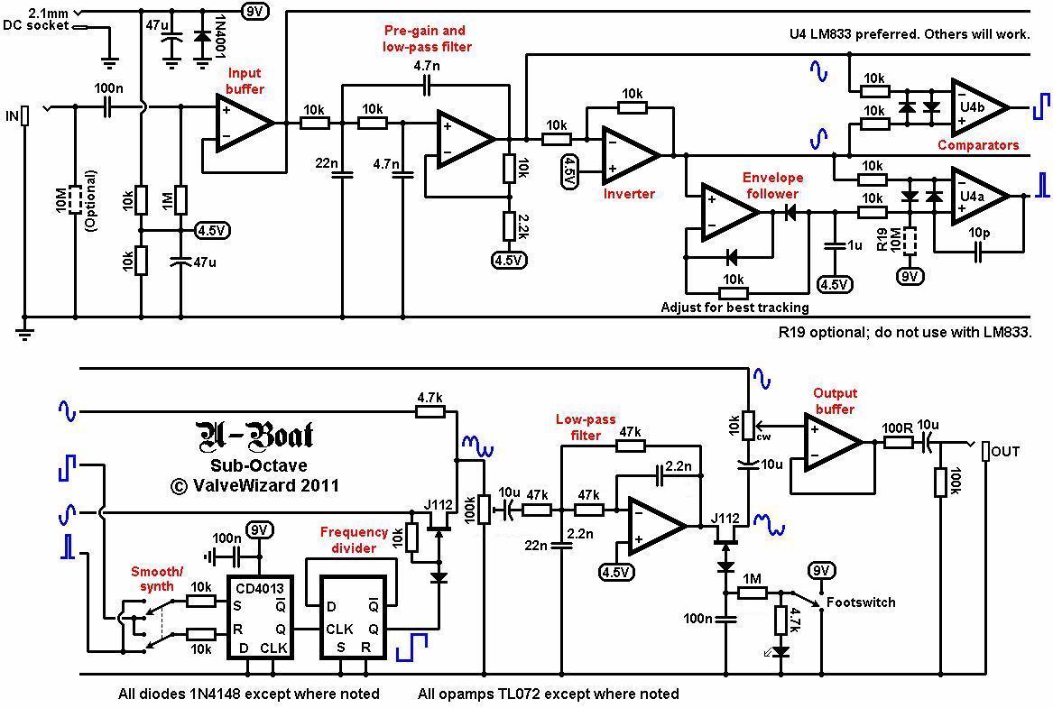
Looking at the U-Boat circuit, the first opamp simply buffers the incoming guitar signal. From here it splits into two paths;
one goes directly to the output buffer (so this is just the original dry signal), while the other goes to a low-pass filter.
The second opamp is a second-order low-pass filter that cuts freqiences above about 1kHz (pretty much the top of the fretboard)
to help remove string harmonics that spoil tracking. This stage also amplifies the signal by a factor of about x4.5 (13dB). This is required to make the signal
as big as possible (but without clipping) to make it easier for the detection stage to handle reliably. In other words, for
good tracking you need to make the small wiggly guitar signal as much like a big, pure sinewave as possible (running the guitar
through a compressor before a sub-octave effect can help in this regard).
After the filter the signal splits into two paths; one is untouched while the other is inverted by another opamp.
We now have balanced signals, which are sent to a zero crossing detector U4b. This is just an opamp
used as a low slew-rate comparator, which produces a square wave output. By feeding it balanced signals we get twice the resolution and more accurate zero
crossing detection without exceeding headroom.
At the same time, one of the filtered signals (it doesn't matter which, but for layout reasons I used the inverted one)
is sent to a peak level detector. This section produces a DC reference voltage that ideally floats just below the peaks of the audio signal.
This DC voltage is then compared with the audio by another opamp comparator U4a, which produces a short pulse every time an audio peak
rises above the DC reference. In other words, these two opamps together for a peak detector that produces a pulse every time there is
an audio peak.
The signals from the comparators are then sent to a CD4013 SR latch. In smooth mode, each time there is a zero crossing the latch is set and remains
that way until an audio peak occurs, at which point it is reset. Untimately the aim is to produce a square wave at the output which is
exactly in phase with the audio, without any spurious tracking errors. The DPDT switch reverses the set/reset order, so the output square wave is 90
degrees out of phase with the audio (synth mode).
The output square wave is then sent to the other half of the 4013 which is arranged as a D flip-flop that divides the
square wave frequency by two. This is used to drive a JFET analog switch.
The analog switch, therefore, alternately selects either the in-phase or out-of-phase audio signals at half the original audio frequency. This effectively chops up the audio and
stitches it together again in the manner described earlier; we finally have sub-octave! But it contains some
clicks and hash from the chopping and stiching process.
The signal therefore passes via a trimpot (with controls the volume of sub-octave) through another low-pass filter.
Finally the sub-octave is ready to be mixed with the original dry signal, and sent to the last opamp which is simply an output buffer.
The second JFET is another analog switch. When the gate is pulled high the JFET is on (low
resistance) and the effect is active. When the gate is pulled low the JFET turns off (very high resistance) and the sub-octave
is effectively silenced, bypassing the effect. The J113 or J201 should also work.
Tracking is very dependent on the opamp used for the comparators (U4). I tried a lot of devices and found the LM833 performed best.
The NE5532 seems to be a good choice too. Other BJT-input opamps will work, but none quite gives the good tracking as the LM833.
A TL072 can also be used but tracking is distinctly poorer (but adding R19 helps). Note that a real comparator is not suitable as it will
switch too fast and cause many glitches.
 Technical details:
Input impedance = 1M ohms
Output impedance = 100 ohms
Current consumption = 15mA when active.
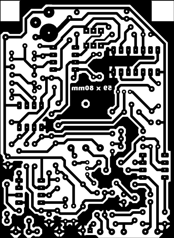
You will find the schematic, PCB layout and BOM here (325kB).
Note: If you print the PCB layout make sure your printer settings are set to "zero page scaling".
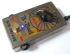
I built mine into an Evatron enclosure, but they don't appear to make them anymore.
However, it should also just fit into a Hammond 1590B
if you shave a little off the sides. Those with a comercial interest in this circuit should contact me.
Soundclip: Played directly into computer sound card with some EQ for a cab sim. Notice that I actually let the notes ring out to demonstrate the tracking, something that virtually all other sub-octave clips avoid!
A professional PCB for this circuit is now available from TH Custom Effects in Germany (no electronic bypass):
TH Custom Effects
|