The Effect of the Screen Grid
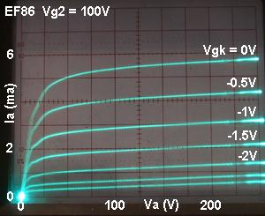  |
Above left: The EF86 characteristics at a fixed screen voltage of 100V. Note that the knee is well defined, and the input sensitiviy is lowest: If centre biased it would take roughly a 4Vp-p input signal to cause clipping.
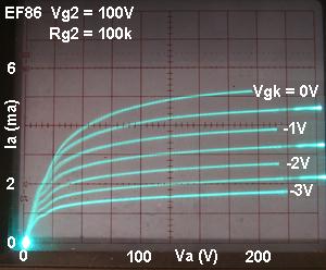
Above right: Using the same screen voltage but inserting a 100k screen-stopper. The screen current causes a drop across the resistor during signal conditions, dynamically reducing the screen voltage in antiphase with the input signal. The knee is now softer, and the transconductance is now quite constant, indicating a great reduction in non-linearity thanks to this screen current feedback. The input sensitivity is reduced, however, and the possible output signal swing may also be reduced when using an unbypassed screen resistor, depending on the load being used. Also note the small 'kinks' in the curves around Va = 20V, these are probably due to brief 'spurts' of secondary emission causing the average screen current to increase momentarily. The same 'kinks' can be seen in the published characteristics of many power pentodes. Note: These are dynamic characteristics; they only apply during signal conditions. For chosing quiescent conditions / bias points we must still use the characteristics above left. Why? Because there can't be any screen compression effects unless there is a signal to compress!
|
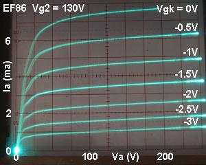
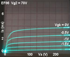
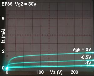
Below: These oscillograms show the effect of altering the screen voltage on a pentode. As it is progressively reduced, the gm (and therefore the voltage gain) progressively falls, while the input sensitivity increases. The basic 'shape' of the curves remains broadly the same, but the grid curves get 'squashed down'. Recognising and understanding this effect is fundamental to understanding pentodes / tetrodes, and immediately makes you about twice as knowledgeable as most guitar 'amp techs'! |
 |
 |
 |
 |
|