|
Compact Moving-Magnet Phono Stage PCB
About:

Following the success of my universal amplifier PCBs I have decided to add a phono PCB for those undertaking hi-fi projects.
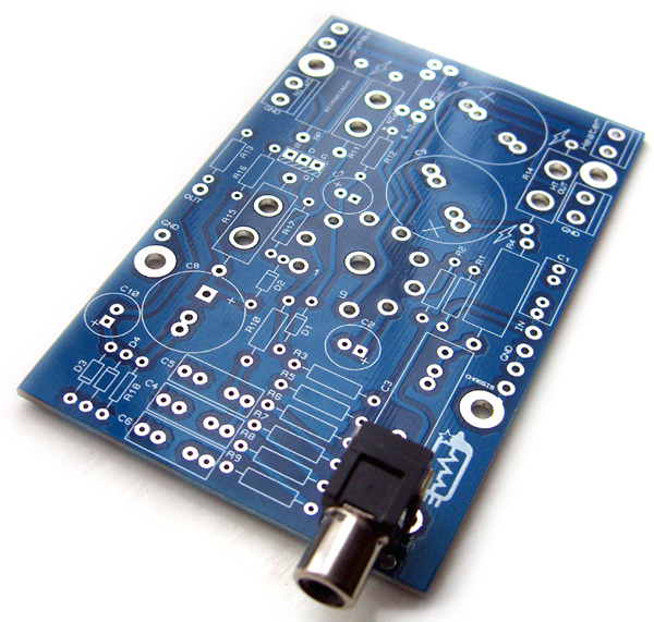
This board allows you to build a compact, mono, moving-magnet phono stage, so you need two boards for stereo.
It is packaged in exactly the same format as the other universal PCBs at just 63 x 100mm, so it can be daisychained along with them if desired.
As with my older three-valve phono stage, the small size is acheived by judicious choice of components;
only using power-resistors and high-voltage caps where absolutely necessary, and avoiding unecessarily oversized 'audiophile' components.
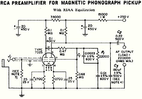
The circuit is based on the well-known RCA tube manual 12AX7 phono stage shown below, but it has been brought up to date with some ValveWizard enhancements.
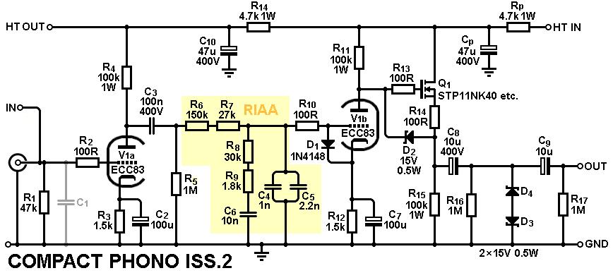
The output is buffered with a MOSFET source follower to provide the low output impedance needed to drive the outside world.
Of course, you can omit this if you prefer, by jumpering across the MOSFET pads.
Sandwiched between the two triodes, the original RIAA equalization circuit has been substituted with the preferred arrangement found in most modern designs,
which naturally works with the Miller capacitance of the second triode.
Finally, the output coupling uses the ValveWizard preferred method of double-coupling with Zener clamping;
this allows large but cheap output capacitors to be used to maintain low output impedance at low frequencies and avoid capacitor distortion,
while the Zeners also protect any following equipment from high voltages, something which most designs fail to address.
You need to provide a power supply for the board of course (the HT / B+ voltage must be less than 450Vdc).

Although the circuit example below shows an ECC83/12AX7, other pin-compatible valves can be used if you prefer, including the popular ECC88/6DJ8
(however, the ECC82/12AU7 is not recommended as it has too little gain to deliver a decent signal-to-noise ration with all-in-one RIAA equalisation).
R6 and R7 will need to be adjusted to suit.
As with my other universal amp PCBs, pin-9 can be configured as a heater pin or be grounded, depending on the tube type chosen.
PCB Features:
The board accepts many PCB-mount B9A valve sockets (pin width up to 1.7mm);
Capacitor sites have multiple pads to allow different package styles to be used;
Multiple resistor / capacitor sites are provided for RIAA equalisation so critical values can be trimmed;
It includes all the expert features you'd expect from a ValveWizard circuit, including grid stoppers, arc and overvoltage protection diodes, and build-out resistor.
Drilling the chassis is a breeze:
There are four holes for mounting the board to the chassis using standoffs.
Just place the board on the metalwork before you start, then poke a pen through the holes to mark their positions on the chassis.
There is also a hole in the centre of the valve socket site so you can mark the position of the valve. Now get drilling! Simple.
(You could also use this hole to mount a 3mm LED for a cool up-lighter effect...)
The image below shows the full schematic with recommended part values assuming a 12AX7 / ECC83.

Technical details:
Current consumption = Typically 5 to 6mA per channel;
Input Resistance = Typically 47k;
Input Capacitance = Typically 200pF;
Output Impedance = Typically less than 700 ohms;
Gerber files
I no longer sell PCBs but you can find the gerber files here.
|