|
3-Valve Moving-Magnet Phono Stage PCB
**PCB no longer stocked, see alternative**
About:
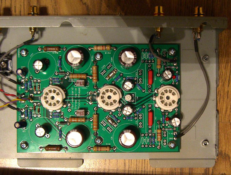
This board allows you to lay out a professional quality, three-valve, stereo, passive-EQ phono stage.
Despite using three valves the overall size is quite small. This is acheived by judicious choice of components; only using power-resistors where absoultely necessary, and avoiding unecessarily oversized 'audiophile' capacitors
-this is very much an 'engineer's amplifier'.
The circuit topology is predefined but the design is flexible enough for you to experiment with various circuit details.
You can either develop your own design from scratch using information from my book, where a very similar circuit is presented,
or you can use the component flow chart (link at the bottom of the page).
The flow chart allows you to build up a full set of component values to suit your choice of valves, cookbook style, with no brain power required!
You need to provide a separate power supply (the HT / B+ voltage must be less than 350Vdc, and the heater current must not exceed 1.2A).
Overview:
The basic circuit topology is classic, consisting of three valves: input stage, second gain stage, and DC-coupled cathode follower.
The cathode follower is essential to ensure a low output impedance for driving cables.
The valves must be dual triodes of the popular pin-compatible type, e.g. ECC81 / ECC82 / ECC83 / ECC88 / 12AT7 / 12AU7 / 12AX7 / ECC88 / 6N1P and so on.
Pin-9 of each valve socket has its own test pad so it can be left floating or be connected to ground, depending on the valve type chosen -see the component flow chart.
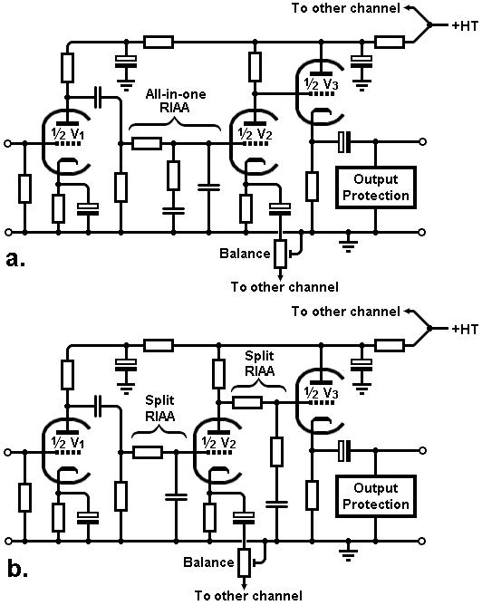
The RIAA equalisation can be set up for all-in-one-go (upper diagram) or split (lower diagram) passive equalisation (type-I, see section 10.3 of my book).
Since valves are never perfectly matched between sections, the second stage has the option for a balance trimmer to allow fine adjustment of left / right gain.
PCB Features:
The board accepts PCB-mount sockets with a 22mm-diameter pin arranement, pin width up to 1.5mm;
Capacitor sites have multiple pads to allow different package styles to be used;
Multiple resistor / capacitor sites are provided for RIAA equalisation, so critical values can be trimmed;
Includes all the expert features you'd expect from a ValveWizard circuit, including grid stoppers, arc protection diodes, and build-out resistors;
Heaters can be connected in series or parallel using jumper links (total heater current must be less than 1.2A owing to track thickness);
Output over-voltage protection is catered for -this is essential yet all too often ignored even in 'professional' designs;
The PCB is 10 x 15cm, and 1.6mm thick.
Drilling the chassis is a breeze:
There are six holes for mounting the board to the chassis using standoffs.
Just place the board on the metalwork before you start, then poke a pen through the holes to mark their positions on the chassis.
There is also a hole in the centre of each valve socket site so you can mark the positions of the valves. Now get drilling! Simple.
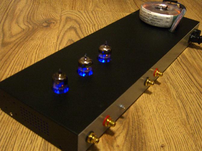
(You could also use these holes to mount 3mm LEDs for a cool up-lighter effect...)
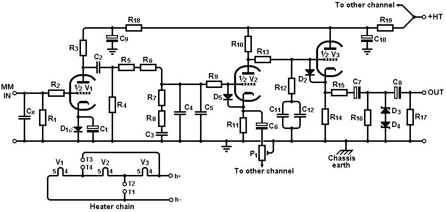
The image below shows the full schematic for one channel with all the available component sites, not all of which will be used in a single design.
The components in the other channel have a 2 in front, e.g R15 in this channel is equivalent to R215 in the other channel.
Technical details:
Current consumption = Typically 20 to 30mA;
Input Resistance = Typically 47k;
Input Capacitance = Typically 50 to 200pF;
Output Impedance = Typically less than 700 ohms;
You can find a full schematic, PCB layout and other design information in the user manual.
You can find the issue.2 component flow chart here.
Gerber files
I no longer sell PCBs but you can find the gerber files here.
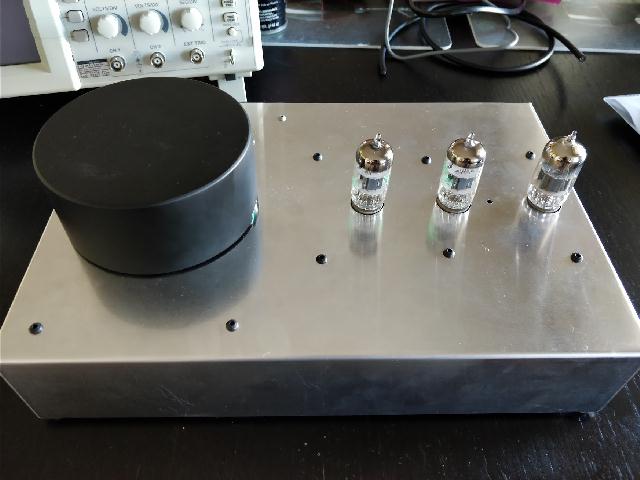
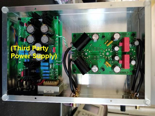
User Examples
|