|
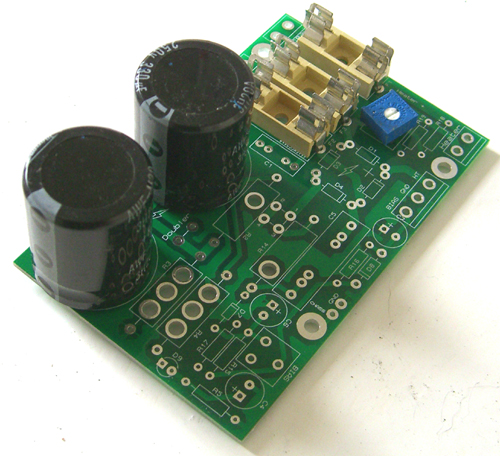
Power Supply PCB (ISS.2)
 The power supply PCB has everything you need for heater, bias, and HT (B+) supplies:
HT (B+):
The maximum AC input voltage is 350V rms (or 350-0-350V), allowing you to generate an HT of about 450V DC max.
There is space for 20mm fuses in both AC supply lines (you only need one if your transformer has no centre tap, of course).
A snubbing network is also included to reduce rectifier switching noise -not essential but nice to have.
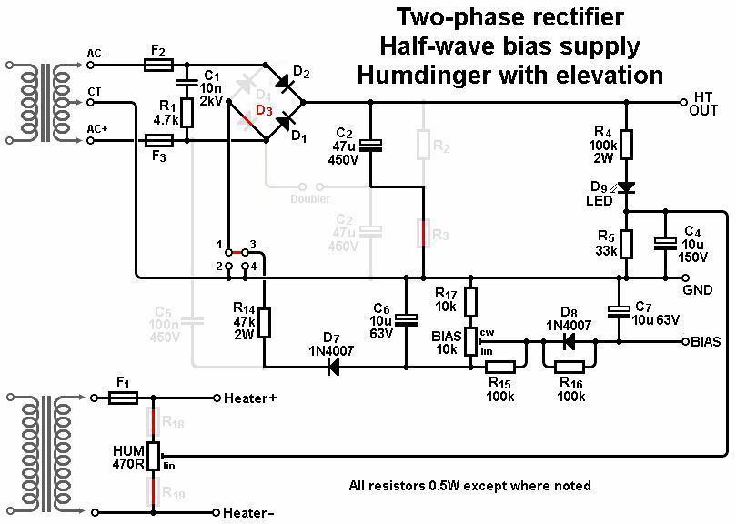
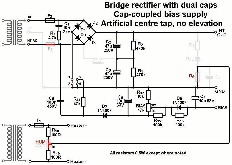
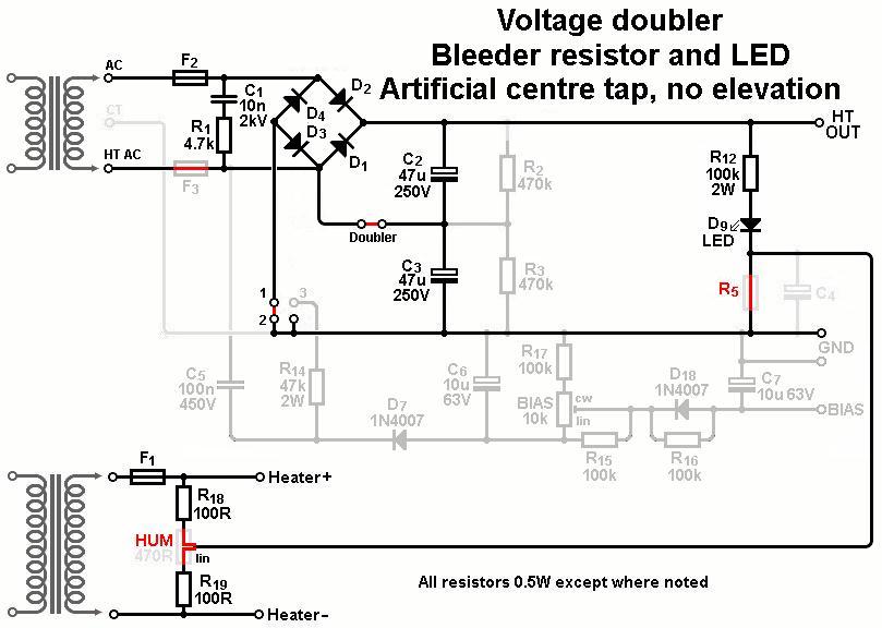
The board can be built with either a traditional two-phase rectifier, bridge rectifier, or voltage doubler.
You can use either discrete diodes or a bridge rectifier package -yes, in any of the above rectifier configurations!
Bias Supply:
The bias supply can be configured either as a traditional half-wave or full-wave supply, or as a capacitor-coupled supply if your transformer has no centre tap.
A trimpot allows bias adjustment and there is also a slow-discharge diode (D8) so the bias voltage persists after the amp is switched off, which helps to prevent accidental fuse pops if the power is flipped off and on too quickly.
Heater Supply:
The heater supply (up to 3 amps) can be configured with an artificial centre tap or a humdinger trimpot, and both can be elevated from the HT.
The elevation divider can also be used to light an LED to show the HT is energised.
Some example circuits are shown below.


For the old iss.1 PCB circuit with VVR click
here and
here
Gerber files
I no longer sell PCBs but you can find the gerber files here.
|