|
Universal Dual-Triode Output PCB
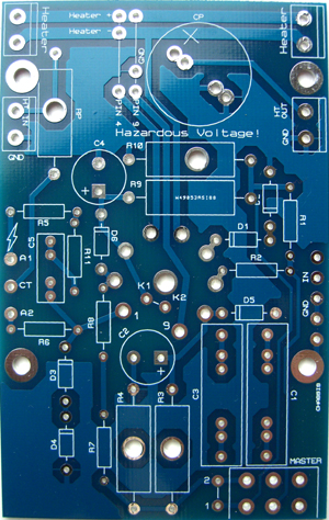 This PCB allows you to build a mini push-pull output stage using a comon dual triode (the 12AU7 works well).
This is ideal for a small practice amp or tone amp, a headphone amp, or a reverb driver.
There are three basic configurations possible with this PCB, as explained below.
Other features include:
This PCB allows you to build a mini push-pull output stage using a comon dual triode (the 12AU7 works well).
This is ideal for a small practice amp or tone amp, a headphone amp, or a reverb driver.
There are three basic configurations possible with this PCB, as explained below.
Other features include:
Input coupling caps. These aren't needed if you're also using one of my other PCBs which already has output coupling caps,
but you may need them if using this PCB on its own for special projects;
Catching diodes between grid and cathode to prevent blocking distortion (described in my book, section 4.19);
Zobel network to tame transformer resonance;
Catching diodes from anode to ground to help protect against negative flyback spikes on the output transformer (use 1N4007);
Anode stopper resistors, to damp oscillation or providing a way to measure anode current.
Cross-Coupled Output Stage
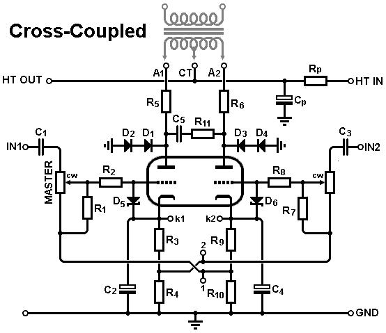 The default circuit is a push-pull amp with balanced inputs, including a dual-gang master volume (optional if you jumper the pads).
What's unusual about this circuit is that it uses cross-coupled cathode bias (some people call this 'Garter bias').
This is a smart way to force the idle currents in each triode to match almost exactly, even if the triodes are quite mismatched.
Each triode effectively servos the other one, resulting in an idle current that is the average of the currents we would ordinarily get without cross coupling.
They will also remain closely matched with age, which is exactly what we want to minimise DC offset in the output transformer.
R3 and R9 are selected to be the usual bias resistors and, once chosen, they must be stacked upon two more identical resistors R4 and R10.
Of course, this wastes some available voltage and therefore reduces the available output power, which is why you don't see this sort of biasing very often.
But for a mini power stage this is unlikely to matter, so give it a try!
The default circuit is a push-pull amp with balanced inputs, including a dual-gang master volume (optional if you jumper the pads).
What's unusual about this circuit is that it uses cross-coupled cathode bias (some people call this 'Garter bias').
This is a smart way to force the idle currents in each triode to match almost exactly, even if the triodes are quite mismatched.
Each triode effectively servos the other one, resulting in an idle current that is the average of the currents we would ordinarily get without cross coupling.
They will also remain closely matched with age, which is exactly what we want to minimise DC offset in the output transformer.
R3 and R9 are selected to be the usual bias resistors and, once chosen, they must be stacked upon two more identical resistors R4 and R10.
Of course, this wastes some available voltage and therefore reduces the available output power, which is why you don't see this sort of biasing very often.
But for a mini power stage this is unlikely to matter, so give it a try!
Differential Output Stage
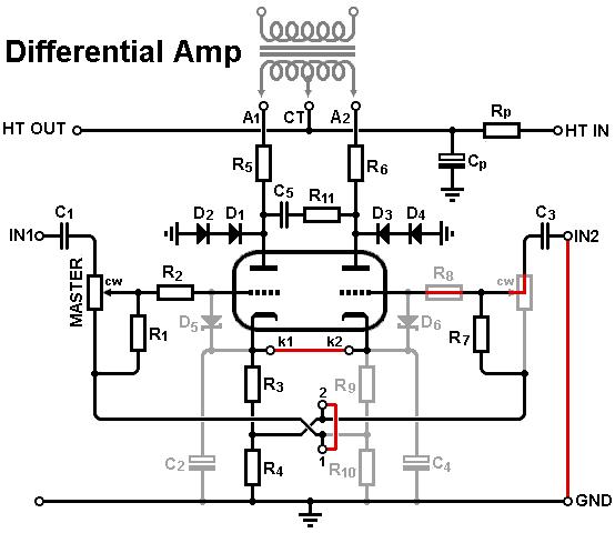 The second option is a classic differential amplifier.
This is accomplished by linking the two cathodes together as indicated by the red links, and also by linking the two grid leaks together with pads 1 and 2.
This is basically a long-tailed pair, but driving an output transformer.
This means the circuit will accept a single input signal and provide it's own phase inversion for push-pull operation, just like any LTP.
This could be a useful space saver in a small circuit, since no addition phase inverter is needed.
Alternatively, being a differential amplifier, you can provide balanced input signals and take advantage of the circuit's superior CMRR.
The second option is a classic differential amplifier.
This is accomplished by linking the two cathodes together as indicated by the red links, and also by linking the two grid leaks together with pads 1 and 2.
This is basically a long-tailed pair, but driving an output transformer.
This means the circuit will accept a single input signal and provide it's own phase inversion for push-pull operation, just like any LTP.
This could be a useful space saver in a small circuit, since no addition phase inverter is needed.
Alternatively, being a differential amplifier, you can provide balanced input signals and take advantage of the circuit's superior CMRR.
Self-Split Output Stage
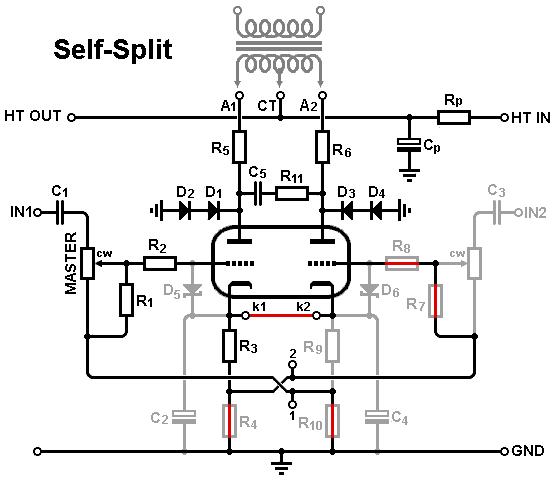 The third option is a stripped-down differential amp, sometimes called a 'self-split' arrangement or even a 'short-tailed pair'.
Here both triode share a single common-cathode bias resistor (R3) and nothing more.
This results in worse AC balance since the first triode has to work as an amplifier and a very crude cathode follower,
and therefore output power is reduced and efficiency is poor, but parts count is low.
But again, in a mini output stage this may not matter to you.
You may have seen this arrangement used in Doug H's Firefly.
The third option is a stripped-down differential amp, sometimes called a 'self-split' arrangement or even a 'short-tailed pair'.
Here both triode share a single common-cathode bias resistor (R3) and nothing more.
This results in worse AC balance since the first triode has to work as an amplifier and a very crude cathode follower,
and therefore output power is reduced and efficiency is poor, but parts count is low.
But again, in a mini output stage this may not matter to you.
You may have seen this arrangement used in Doug H's Firefly.
Gerber files
I no longer sell PCBs but you can find the gerber files here.
|