|
Universal Tremolo PCB
 This PCB allows you to make one of three different tromolo circuits.
In each case the low-frequency oscillator (LFO) is a fairly standard phase-shift oscillator.
A footswitch or panel switch can be used to switch the LFO on or off, or you can leave it running all the time and just use the tremolo depth control.
The second triode can be arranged as a gain stage or cathode follower as explained below.
This PCB allows you to make one of three different tromolo circuits.
In each case the low-frequency oscillator (LFO) is a fairly standard phase-shift oscillator.
A footswitch or panel switch can be used to switch the LFO on or off, or you can leave it running all the time and just use the tremolo depth control.
The second triode can be arranged as a gain stage or cathode follower as explained below.
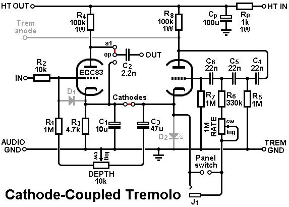 The first option is a self-contained tremolo like the one found on the Kalamazoo Model Two.
In this arrangement the low-frequency oscillator is cathode-coupled to an ordinary gain stage.
As the cathode voltage (e.g. the bias voltage) oscillates it causes the gain of the audio stage to rise and fall, producing tremolo (amplitude modulation).
A small bypass capacitor (C1) prevents cathode feedback at audio frequencies which would otherwise fight this gain variation, but it is too small to bypass the oscillator frequency which is less than 10Hz.
The depth of modulation is controlled by introducing a larger cap (C3) which does bypass the oscillator frequency, gradually preventing the cathode voltage from varying.
This circuit has the advantage that it needs no special parts, only standard resistors and capacitors.
However, there are some disadvatages. First, the tremolo effect is quite mild because the gain of 12AX7 does not vary much with bias.
Second, the DC anode voltage pulsates along with the oscillator, causing throbbing or ticking unless it is filtered out with some heavy bass-cut, e.g. a small output capacitor.
The first option is a self-contained tremolo like the one found on the Kalamazoo Model Two.
In this arrangement the low-frequency oscillator is cathode-coupled to an ordinary gain stage.
As the cathode voltage (e.g. the bias voltage) oscillates it causes the gain of the audio stage to rise and fall, producing tremolo (amplitude modulation).
A small bypass capacitor (C1) prevents cathode feedback at audio frequencies which would otherwise fight this gain variation, but it is too small to bypass the oscillator frequency which is less than 10Hz.
The depth of modulation is controlled by introducing a larger cap (C3) which does bypass the oscillator frequency, gradually preventing the cathode voltage from varying.
This circuit has the advantage that it needs no special parts, only standard resistors and capacitors.
However, there are some disadvatages. First, the tremolo effect is quite mild because the gain of 12AX7 does not vary much with bias.
Second, the DC anode voltage pulsates along with the oscillator, causing throbbing or ticking unless it is filtered out with some heavy bass-cut, e.g. a small output capacitor.
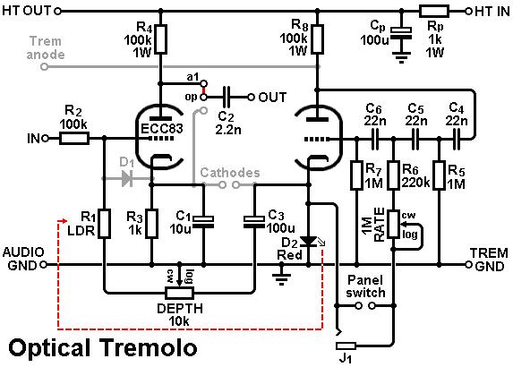 The second option is a self-contained optical tremolo.
The oscillator uses a LED for biasing, which will therefore flash along with the oscillations.
The LED must point towards a light-dependent resistor (LDR) that forms a potential divider at the input of the gain stage.
(The pair must be shielded from ambient light with heatshrink or similar). When the LED shines bright the LDR resistance goes low, attenuating the audio, and vice versa.
The depth is controlled in two ways at once.
As the pot is turned it gradually bypasses the LED with C3, to reduce the depth of flashing.
It also adds resistance in series with the LDR, so the audio cannot be attenuated as much.
This circuit has the advantage that it produces a very deep tremolo effect with less throbbing/ticking.
In fact, the only ticking is caused by the LFO modulating the power supply node, so by using a small dropping resistor (Rp) and a big smoothing capacitor (Cp) it can be effectively suppressed.
The disadvantage is that you need an LDR which is not a standard part anymore, but they are available on eBay from China, for example.
Almost any LDR will work; simply adjust R2 to get the maximum depth you want.
The second option is a self-contained optical tremolo.
The oscillator uses a LED for biasing, which will therefore flash along with the oscillations.
The LED must point towards a light-dependent resistor (LDR) that forms a potential divider at the input of the gain stage.
(The pair must be shielded from ambient light with heatshrink or similar). When the LED shines bright the LDR resistance goes low, attenuating the audio, and vice versa.
The depth is controlled in two ways at once.
As the pot is turned it gradually bypasses the LED with C3, to reduce the depth of flashing.
It also adds resistance in series with the LDR, so the audio cannot be attenuated as much.
This circuit has the advantage that it produces a very deep tremolo effect with less throbbing/ticking.
In fact, the only ticking is caused by the LFO modulating the power supply node, so by using a small dropping resistor (Rp) and a big smoothing capacitor (Cp) it can be effectively suppressed.
The disadvantage is that you need an LDR which is not a standard part anymore, but they are available on eBay from China, for example.
Almost any LDR will work; simply adjust R2 to get the maximum depth you want.
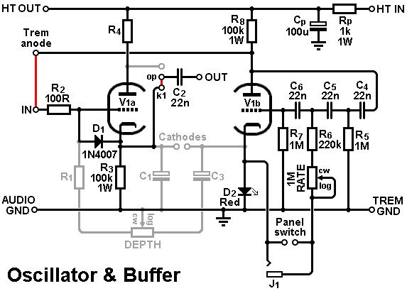 The third option is to use this PCB purely as an oscillator and buffer.
The second triode is used as a DC-coupled cathode follower which can then be used to modulate the bias voltage in a fixed-biased output stage.
Take a look at the Fender VibroChamp, 6G3, or 6G9 Tremolux for ideas (a depth control would need to be added off board).
The third option is to use this PCB purely as an oscillator and buffer.
The second triode is used as a DC-coupled cathode follower which can then be used to modulate the bias voltage in a fixed-biased output stage.
Take a look at the Fender VibroChamp, 6G3, or 6G9 Tremolux for ideas (a depth control would need to be added off board).
See the shop page for pricing.
|